ARC 3.5m | KOSMOS
Last update, new slits and kcam focus: Oct 24, 2024 - RM
Table of Contents
KOSMOS (Kitt Peak Ohio State Multi-Object Spectrograph) is a medium dispersion spectrograph (resolving power up to 2600) using grism dispersers. It was built at Ohio State and commissioned at the Kitt Peak Mayall 4-m telescope in October 2013, then later converted for use at the Apache Point Observatory ARC 3.5m Telescope with re-commissioning in October 2021. Since the spectrograph was originally designed for a faster telescope beam than the ARC 3.5m, slits that provide optimal spectral resolution will lose some starlight with typical site seeing, while slit sizes that sample starlight more thoroughly will result in lower resolution. The instrument can also be used in imaging mode.
The instrument conversion for use at APO includes a larger dewar, redone electronics, a calibration stage with internal arc and quartz lamps for calibration while the instrument is off the telescope, and a slitviewer for target acquisition and guiding.
Imaging mode is set up by having both the disperser wheel and the slit wheel set to empty positions. The full telescope field is available, giving a field of view of >7 arcmin. In this mode, only a part of the detector is illuminated with a round aperture. The spatial scale is 0.258"/pixel, and the outer edges of the image do not receive illumination from the sky.
Image quality and detector sensitivity is comparable to ARCTIC, but KOSMOS's more limited filter capacity and long readout time of 50s means that ARCTIC is useful for a wider range of imaging purposes. In some cases, particularly in good seeing conditions, imaging mode might be used for focusing the telescope on the instrument, because the slitviewer optics and plate scale make it less sensitive to fine adjustments in telescope focus.
There are two filter wheels located after the disperser wheel and before the camera, tilted to reduce internal reflections. As of mid-March 2022, the only filters loaded are broad filters intended for spectroscopic order-blocking. There is also an ND5 filter for observing very bright targets, which may be used by itself or in combination with a blocking filter in the other wheel. The wheels take 4-inch square or round filters, which are not a common size in our Filter Database, but some smaller filters might be possible to adapt to fit KOSMOS. Please communicate with APO at least a month in advance of requesting a filter that is not already loaded.
Default filters loaded in KOSMOS:
Filter Name Bandpass Filter 1 Position Filter 2 Position
In spectroscopic mode, both a slit and disperser are added to the instrument's light path; the combination of slit+disperser determines the wavelength range for the resulting spectrum. The spatial scale along the slit will be 0.258"/pixel, same as in imaging mode.
The disperser wheel has slots for 6 dispersers, but as of February 2022 only two grisms are available: red and blue. Wavelength range may be further adjusted by selecting a different slit position. Three slit positions are available: low, center, and high. The "low" slit position delivers shorter wavelengths and also appears lower in the slitviewer field of view, while "high" delivers longer wavelengths and appears higher on the slitviewer.
The motors for the KOSMOS slit wheel and disperser wheel are very fast and repeatable, making it possible to use more than one spectroscopic setup in a night, and it's even feasible to change back and forth between setups on each target. However, changing slits will necessitate re-slewing and re-centering the target, which can cost a significant amount of overhead time. Therefore the most efficient use of multiple setups would include keeping the same slit and changing between grisms to get a different wavelength range; with this approach, it's possible to keep guiding on the slitviewer while the grism is moving, and begin a new exposure as soon as the disperser wheel finishes moving. The alternative strategy of switching from the blue grism with a low slit position to the red grism with a high slit position would offer maximal wavelength coverage, but because of the need to re-acquire targets this method would only be effective for a small number of setup changes in a night.
Your choice of grism, slit position and slit width should be specified in your observing proposal and explicitly be confirmed by email with the observing specalists (35m-observing@apo.nmsu.edu) several days prior to your observing time.
Unbinned KOSMOS images are 2048 pixels in X and 4096 in Y (not including overscan), with X being the spatial direction and Y being the dispersion direction. Short wavelengths are at the top of the image and longer wavelengths at the bottom.
The slit wheel has 6 positions, with one position normally kept empty for imaging mode and one position reserved for a grid of pinholes to be used for checking spectrograph focus. For long slits, the standard slit length is 6 arcminutes. The tilted, reflective slits are pre-loaded into holders with non-reflective blanks blocking off unused slit positions; observing staff are not trained to move a particular slit to a different position. We have a variety of reflective slits available, with the most popular ones being a 1.18" slit (only available in the center position as of February 2022), a set of approximately 0.85" slits (available in all three positions), and a set of approximately 2" slits (available in all three positions). Other slits smaller than 0.85" or larger than 2" are also available; see full list below.
In addition, we have some non-reflective long slits which sit flat in the focal plane instead of sending light to the slitviewer. As of early February 2022, observing staff is unpracticed at target acquisition and guiding without using the slitviewer, but this option is available with advance notice. Short multi-object slits (also non-reflective) may be designed for specific target fields, but this must be planned with a lead time of a few months and the observing methodology has not been tested yet.
Slitviewer-compatible relective slits delivered with KOSMOS:
| ID Number | Position | Effective width | Comments | |
02 |
center |
0.42" |
Broken | |
03 |
low |
0.36" |
Broken | |
04 |
high |
0.58" |
Decommissioned | |
07 |
low |
0.40" |
Decommissioned | |
08 |
center |
0.54" |
Decommissioned | |
09 |
high |
0.42" |
Decommissioned | |
12 |
low |
0.75" |
||
13 |
high |
0.42" |
Decommissioned | |
16 |
center |
0.59" |
Decommissioned | |
17 |
high |
0.66" |
Decommissioned | |
18 |
low |
0.73" |
||
21 |
high |
0.75" |
||
22 |
center |
0.73" |
||
23 |
low |
0.83" |
||
25 |
center |
1.18" |
||
26 |
high |
0.86" |
||
27 |
center |
0.87" |
||
28 |
low |
0.58" |
Decommissioned | |
29 |
high |
2.05" |
||
30 |
center |
2.10" |
||
31 |
low |
2.0" |
||
33 |
center |
7.1" |
||
34 |
high |
7.1" |
||
35 |
low |
7.1" |
||
36 |
center |
1.25" |
Sent back | |
37 |
low |
1.25" |
Sent back | |
38 |
high |
1.25" |
Sent back | |
39 |
center |
20" |
||
40 |
low |
20" |
Needs testing | |
41 |
high |
20" |
||
Pinholes |
5x5 grid |
0.4" |
KOSMOS is operated within the Telescope User Interface (TUI) software written by Russell Owen at the University of Washington. As of February 5, 2022, TUI version 2.6.1a is required for KOSMOS operation; this TUI version is available for MacOS 10.14 up to MacOS 12, and for recent versions of Windows. A TUI Manual is available, and TUI versions may be downloaded here. The linux version 2.6.1a2 on the download page has been tested on Ubuntu 16.04 as of early February 2022, so users of different linux versions may have a different experence; please share information about difficulties and strategies with the observatory so that we can share solutions with other observers.
2.2. Configuring the Instrument
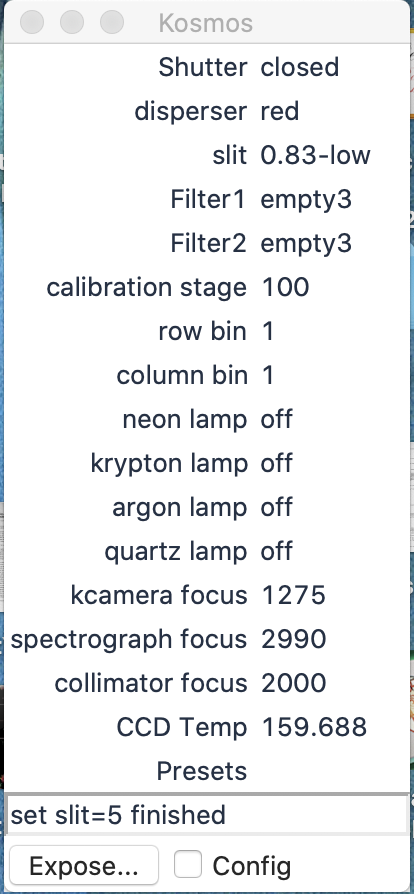
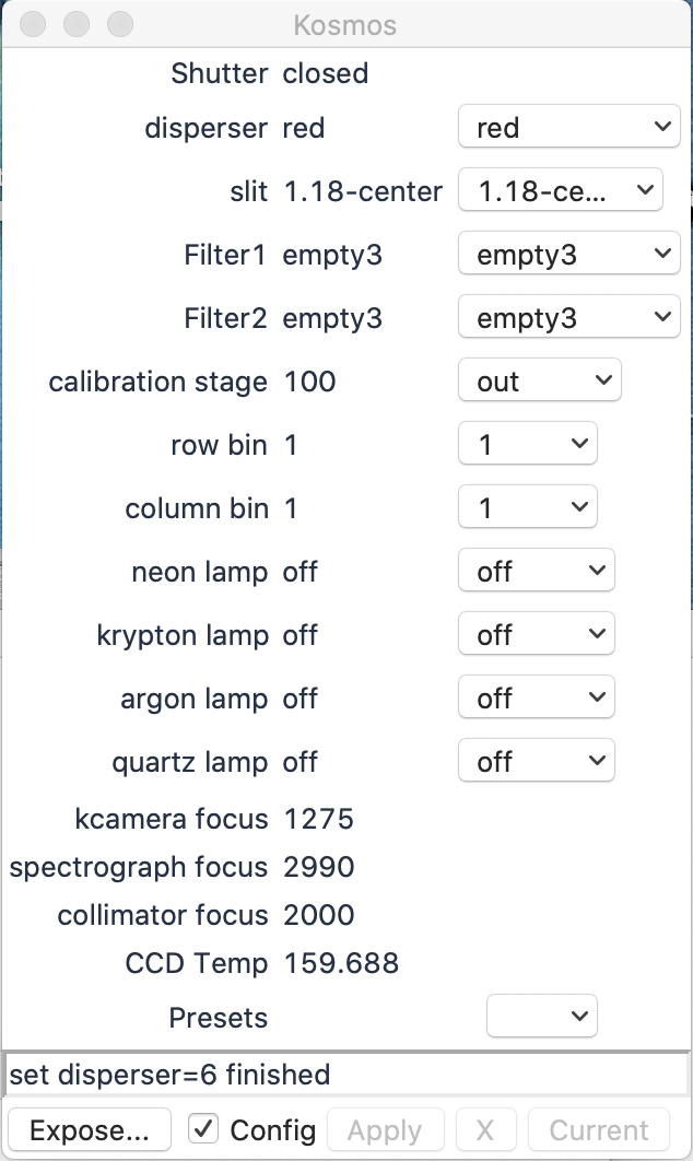
The instrument is configured using the KOSMOS window accessible under the Inst menu from the main TUI window. This brings up the KOSMOS instrument gui. Here we give brief overview of the KOSMOS controls via the KOSMOS instrument gui.
This window shows the current configuration: grism selection, slit selection, filter selection (currently all empty), caltstage position (100=out of beam for sky viewing, 20200=in beam for internal calibrations), CCD binning, lamp states, and internal focus motors (these can only be moved by low-level commands, not through the GUI). Controls for changing the configuration will appear when the Config box is checked. As with other TUI windows, the Apply button must be hit to implement any selected changes and all current selections selections outlined in pink are applied when the button is pressed.
In the 2.6.1a version of TUI, a cosmetic bug may cause pulldown menus to truncate the display of the current status, although the functionality of the pulldowns is still usable. Certain MacOS versions may also have buttons with invisible labels, including the Start button for beginning an exposure. A workaround for this bug that will fix the unlabeled buttons and most of the pulldown menus (including all of the pulldowns in the KOSMOS window) is to open the Preferences menu, select Fonts, change the fontsize and press Apply. You may then change the fontsize back to the previous value if desired, and the fix should remain in place. This trick with the font size must be repeated each time TUI is restarted.
For KOSMOS, unlike most other APO instruments, it is possible to move motors and turn lamps on or off during image readout. It is not possible to change instrument configuration during an exposure. Making a change during readout will not affect the image header, since the instrument configuration reported in the header is captured at the beginning of the exposure rather than end of readout.
There is an option to bin by a factor of 2 in the KOSMOS window. The CCD can be independently binned in either direction to change either the spatial scale (the "column bin" pulldown), the dispersion (Å/pixel, changed with the "row bin" menu), or both. Binning might be advantageous if working in a readout noise limited regime, when shorter readout times are strongly desired, or when using a wider slit, so that degradation of either spatial or spectral resolution is acceptable. Subframing is not currently possible with KOSMOS. The readout time for 1x1 binning is 52s; for column binning x2, 34s; for row binning x2, 29s; for 2x2, readout time is 24s. These times include an allowance for transferring the finished image to the destination directory.
KOSMOS exposures are taken using the Expose gui, which is opened using the Expose button in the KOSMOS instrument gui. The Expose gui looks like this:
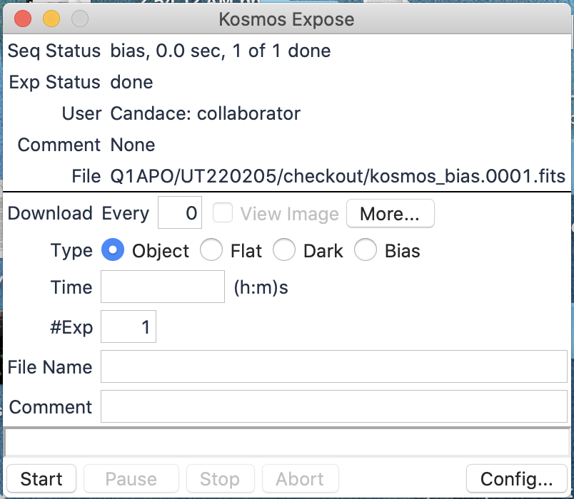
The Expose window is in standard TUI format (for detailed description see here ). It shows status of the current exposure at the top, and allows you to set the object Type (for the FITS image header), exposure Time, number of Exposures, and root File Name. If you wish to add comments to the file header, place them in the Comments field.
All data will automatically be stored on a local computer named arc-gateway in /export/images/<program ID>/<UTdate>/<filename>. This can be accessed with an institution-specific username, for example, uwobserver. The passwords for these usernames change quarterly, and can be obtained from your institutional scheduler (preferred) or by calling APO directly. However, most users set TUI up to automatically transfer images to their local computer using the Preferences - Exposures window in the main TUI menu (setting Get Every to 1 here download images from any instrument) or the More button in the Expose window (setting Get Every to 1 in this window will affect only KOSMOS images). You also can set the directory tree where you want images to go on your local machine, check Get Collab to download images taken by another TUI logged in with the same program name, and remember to Save these settings when you are done changing them. You can also define a subdirectory (TUI will create it for you) by choosing an image name such as <subdir1>/<subdir2>/<filename>; note, however, that a separate image number sequence will be started in each subdirectory.
The FITS header for each image stores exposure information, instrument configuration, and telescope parameters for future reference.
The Start button begins the exposure or exposure sequence.
- Start - This button starts the exposure or exposure sequence.
- Pause - This button DOES NOT WORK, please do not use it (as of February 5, 2022).
- Stop - This button can be used during readout to stop a sequence of images after the readout finishes. As of February 17, 2022, this button will stop an exposure early and write the image to disk; however, it does not update the EXPTIME in the header with the actual value, and there may be some cosmetic oddities in the countdown of the readout. Use with caution.
- Abort - This button DOES NOT WORK and MAY CRASH INSTRUMENT CONTROL SOFTWARE, please do not use it (as of February 5, 2022).
Users should be aware that it is possible to write command scripts with sequences of commands. This can be done either by writing Python scripts for execution by TUI (see TUI documentation), or by writing lists of instrument level commands that can be run from the Run Commands window. This window is in the TUI menu under Scripts. Users can either type in the commands in that window, or read them from an input file. A list of useful instrument level commands will be added to this document when time allows.
2.4. The KOSMOS Slitviewer Camera
There is an internal slitviewing camera in KOSMOS that is used for target acquisition and guiding. The slitviewer camera is a Finger Lakes Instruments CCD camera. The pixel scale depends on the slit position: 0.356"/pix for the high position, 0.347 "/pix for the center position, and 0.330"/pix for the low position. The field of view is approximately 6 arcminutes in the X direction and 3.5 arcminutes in the Y direction. For high and low slit positions, the field of view is limited by the illumination of the telescope so that the corners of the image receive very little light from the sky.
Slitviewer Camera Summary:
- Camera manufacturer Finger Lakes Instruments ML4710
- CCD is an E2V CCD47-10
- CCD pixel size = 13 µm
- CCD read noise = 11 e- / pixel
- Quantum Efficiency ~95% @ 680nm
- Dark Current: 21 e- / second
- Pixel scale = 0.356, 0.347, or 0.330 "/pixel binned 1x1
- Full well depth: 100k e-
- Field of View: 6' x 4'
- Minimum Exposure: 0.3s
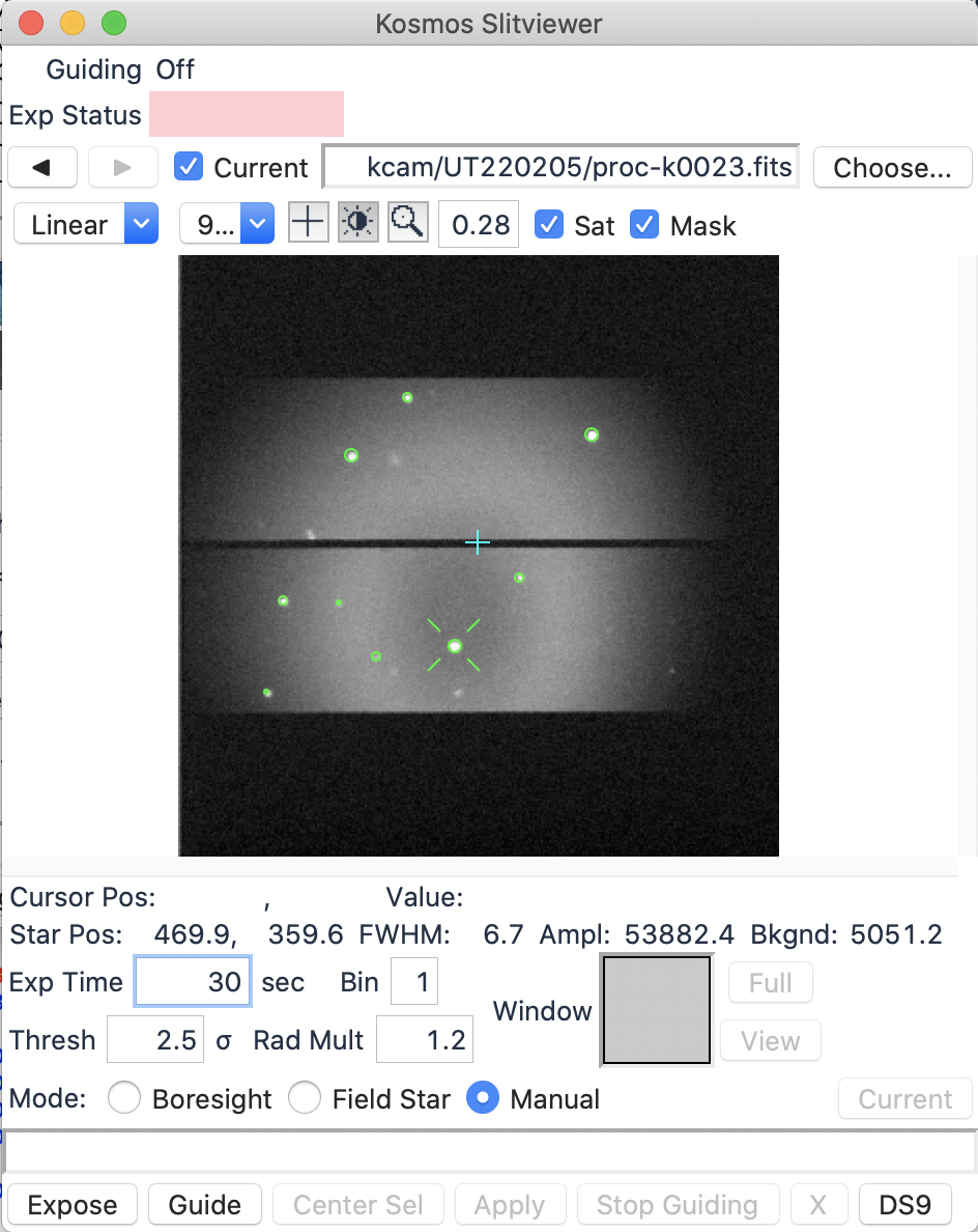
Control of the slitviewer is obtained via the KOSMOS Slitviewer window accessible under the Guide selection in the main TUI menu. The slitviewer gui looks like this with a slit in the center position:
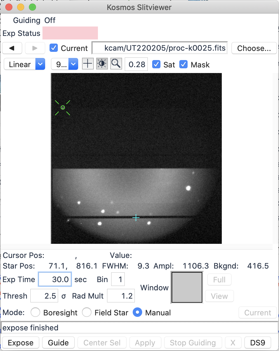
And like this for a slit in the low position:
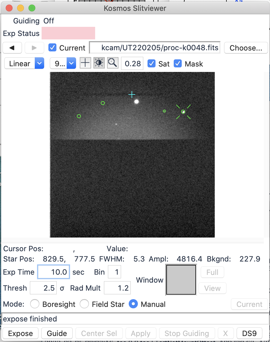
And like this for a slit in the high position:
Just above the image, there are three mode boxes. The first (with a plus symbol) is the cursor mode. In order to select a field star or Center Sel you must be in this mode. The second (with a dark/bright sun symbol) is a contrast mode. Selecting the contrast icon and clicking in the bottom-center area of the image usually improves the illumination pattern; once satisfied, change out of contrast mode to avoid mistakes. The last (magnifying glass) is zoom mode. While in this mode, you can draw a box to zoom and unzoom. To draw a box, click and hold on an area to the top left of the desired area, drag, and release to the bottom right of the desired area. To unzoom partway, draw a box in the opposite direction, lower right to upper left, or double-click to zoom out all the way. If you are using a three-button mouse, the left button will act in cursor mode, the middle button will adjust contrast, and the right button can be used to zoom.
Images are obtained by setting an exposure time and hitting the Expose button. The resulting image will show circles around centroidable objects that may be used for guiding, with an additional X on the default object. To put the cursor on a different object, make sure the + symbol above the image is highlighted, then click on the target if it already has a circle, or CTRL-click on an unmarked position. Once the X is on the desired target, mouse over the Center Sel button without pressing it, and an arrow will be drawn to show the proposed offset to bring the star to the boresight. Pressing Center Sel makes the offset described by the arrow, then takes a fresh image. The location of the slit center is periodically adjusted by the observing specialists but is generally at X position of 512 and a Y position that depends on whether a high, center, or low slit is in use. Always make sure you're looking at a current image before you CTRL-click, Center Sel or start guiding. You must be in cursor mode (+ symbol selected along top control panel on slitviewer) for CTRL-click to function.
The slitviewer is also used for guiding during the spectrograph exposure. As of February 2022 we are still working on flat-fielding and masking the slitviewer images, as we do for other slitviewers at APO. While masks are not yet working, it will not be possible to use Boresight guiding on an object centered in the slit; observers must use Field Star mode to guide on another star in the image away from the slit. Once your science target is on the slit, click on one of the circled stars to mark it as the desired guide star. Once a green X appears on the guide star, make sure the Field Star radio button is selected and then press Guide to begin actively maintaining the telescope position. Manual guide mode takes a loop of images and marks potentially usable objects on each image, but does not send any offsets to adjust the telescope position; if you are using this mode you will need to check images directly and adjust position using the Offset or Nudger gui. Another option is to use Manual mode guiding with the KOSMOS slitviewer and active guiding with the off-axis NA2 guider; ask your observing specialist for help if you want to use this method.
You can guide on any object which is centroidable (galaxies with strong cores are fine), not too faint, and non-saturated. Optical double stars, late-type galaxies, and bipolar PNs may pose a problem for guiding, as will objects where you desire to observe a position away from the bright center (e.g., SNs near bright galaxies). Any object the guide software thinks is usable will be circled in green. If your favored guide object is not circled, it may be too faint, too bright, or too lumpy. If you really want to use an object that has no circle around it, try drawing a box around it to centroid it (in cursor mode with the left mouse button). If this succeeds, a circle will appear, and then you can attempt guiding on that object.
Use longer exposure times to get more stable guiding from your star. The best exposure times are 5-30 seconds, but up to 120 seconds is usable if you can be patient. Longer exposure times can also help if you have data transfer problems. On the other hand, if you are keeping the slit aligned with the parallactic angle by using Horizon rotation, shorter exposures may result in more accurate guiding. See more about guiding in Guiding with TUI Users Guide.
2.5. Telescope and Instrument Focus
The telescope is usually focused by inspection of images on the slitviewer. Because the slit is tilted relative to the focal plane, it is important to place an object near the slit for focusing purposes. As of early February 2022, the plate scale and re-imaging optics for the slitviewer make it relatively insensitive to telescope focus, which means that focusing on the slitviewer will be fast but may not be very accurate. In most cases, the observing specialist will focus by using KOSMOS in Imaging Mode instead; this will be slow because of the long readout time, but should produce better results.
As with all instruments, monitoring focus is advisable. It will change over the course of the night, especially at the beginning of the night before the telescope has reached equilibrium. If you find double-peaked spectra from a stellar target, tell the observing specialist that focus is off.
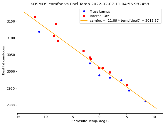
KOSMOS has several motors which control internal instrument focus. These are controlled by the observing specialist with low-level commands, but the focus values are displayed near the bottom of the KOSMOS gui window. Observers have the option to check on these focus values, or ask the observing specialist if they are up to date. Collimator focus should always be set at 2000. Spectrograph focus should be adjusted for the expected dome temperature during the upcoming night, but values around 3050 are appropriate for winter and 2900 for summer (see plot). Kcamera focus depends on which slit position is in use. As of September 2024, the correct values are 1950 for the high slit position, 2050 for the center slit position, and 2350 for the low slit position; these numbers may be adjusted if further alterations are made to the slitviewer.
2.6. Image and Slit Orientation
The orientation of the slit can be set by positioning the image rotator to the desired orientation. This can be done via the Slew window in TUI; note that if you are using User Catalogs (highly recommended, see user catalogs), you can preset the desired position angle using the RotAng= keyword.
Note, however, that specifying a rotation of 0 Object will orient the slit in the E-W direction. Consequently, if you have a desired position angle on the sky in standard usage (PA of 0 corresponds to N/S, PA increasing from N towards E), you need to command a rotation of position angle minus 90 degrees.
At a rotation of 0 Object, right ascension increases to the left on the slitviewer but to the right on the spectrum.
It is possible to configure the rotator to keep a fixed angle relative to the horizon during an exposure. This is done by setting Rot to 90 and Horizon mode in the pulldown menu next to that in the Slew window. The drawback to this method is that the field will no longer be derotated on the sky, so only one point in the field will be stationary and all else will rotate around it. This point is called the boresight. As a result, you must locate your object at the boresight and guide on that position to keep the object in the slit. Guiding in Field Star mode with Horizon rotation does adjust for the expected image rotation, but it will be less accurate than Boresight guiding. Shorter slitviewer exposures can improve the accuracy of guiding with Horizon rotation.
You can always check the slit orientation in the Focal Plane window in TUI. If the instrument is set to KOSMOS, KHIGH, or KLOW, the window shows the orientation of the slitviewer on the sky. If the instrument is set to KIMAGE, the Focal Plane window shows the orientation of images taken with the instrument in Imaging Mode.
If you want to observe at the parallactic angle and have exposures that are not too long, many users find it easier to simply set the rotator to the position angle corresponding to the parallactic angle at mid-exposure, and leave it set at that value throughout the exposure. Again, remember that the commanded position angle needs to be set at 90 degrees from the desired parallactic angle!
The KOSMOS detector is an e2V CCD44-82 2048x4096 back-illuminated device with 18-bit readout. ADC saturation occurs at over 262,000 DN, full-well saturation is at 250,000 DN, and non-linearity begins a little above 200,000 DN.
Spectrograph Camera Summary:
- CCD is an E2V CCD44-82
- CCD pixel size = 15 µm
- CCD read noise = 6 e- / pixel
- Gain = 0.6 e- / DN
- Dark Current: ~1 DN / minute
- Pixel scale = 0.258 "/pixel binned 1x1
- Full well depth: 150k e- = 250k DN
- Minimum Exposure: 0.5s
Estimates of throughput and limiting magnitudes at the time of commissioning in October 2021 were that in imaging mode (unfiltered), the detector could reach 19th magnitude in a 2s exposure. With the red grism and 1x1 binning, the spectrograph could get peak counts above 10 DN for magnitude 17 in 120s and magnitude 19.5 in 1200s. The slitviewer could detect objects of magnitude 17 in 5s and magnitude 19.5 in 1 minute.
For the reported gain of 0.6 electrons per DN and read noise around 6 electrons per pixel, a S:N of 10 would be achieved with 213 DN per pixel. At higher signal levels where Poisson statistics dominate over read noise, the S:N would be closer to the square root of the number of electrons, so that S:N 100 occurs at around 16700 DN.
Delivered throughput will be affected strongly by seeing conditions in comparison with slit width, accuracy of telescope focus, and centering of the star on the slit. On February 5, 2022, with sub-arcsecond seeing and the 2" high slit in use with the blue grism, a 60s spectrum of the standard star Feige 34 (V=11.14) taken immediately after focusing had peak counts in excess of 2000 DN in a well-focused spectrum. On January 30, 2022, with 2" seeing and the 1.18" center slit with both blue and red grisms, the peak counts were 500 (blue) and 900 (red) a few hours after the telescope was focused. Both nights were reported as clear and the star was at similar airmass, so it was likely the seeing, focus, and slit size driving the difference in counts. These effects make a simple exposure calculation challenging, but common exposure times are 1-5 minutes for standard stars, and 20-30 minutes for faint science targets. Exposures longer than 30 minutes are possible but may be inadvisable because of cosmic ray accumulation and also because of the current difficulties with exposure Stop and Abort controls.
Typical KOSMOS calibration exposures include wavelength calibration, flat fields, bias frames, and dark frames. For KOSMOS, internal calibration lamps are available in addition to the lamps on the telescope truss which are used by some other instruments. This means it is possible to take some calibration images with KOSMOS while another instrument is in use on the telescope.
4.1. Calibration Lamps and Control
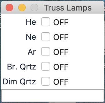
The calibration lamps mounted on the telescope are controlled by the Truss Lamps gui under Misc in the main TUI menu. In contrast with many other TUI controls, these are turned on and off by simply hitting the On/Off buttons; there is no Apply button for these lamps. The Truss Lamps gui looks like this:
The internal calibration lamps are controlled from the KOSMOS gui by selecting a value from the lamp's pulldown menu and then pressing Apply. In order for the light from the lamps to reach the slit, the calibration stage must be in the "in" position, with the motor at 20200. For light from the telescope (either sky light or truss lamps) to reach the slit, the calibration stage must be in the "out" position, with the motor at 100.
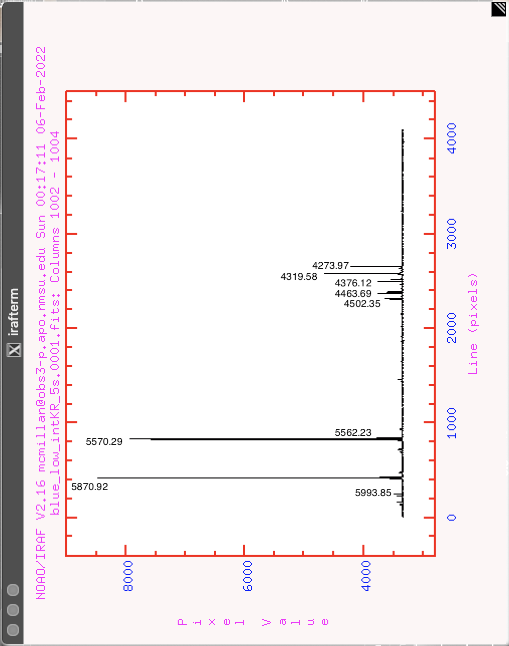
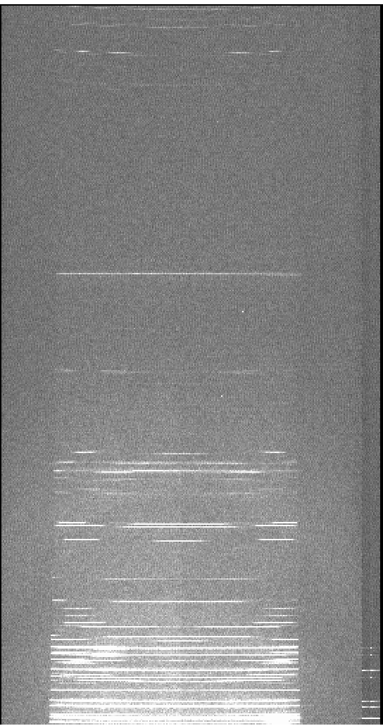
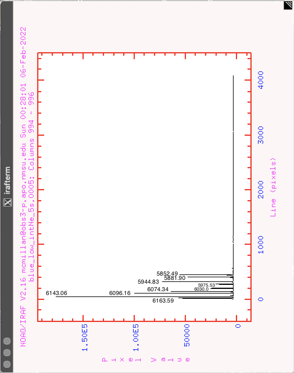
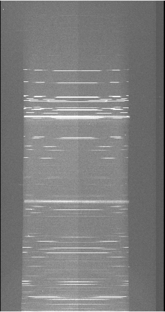
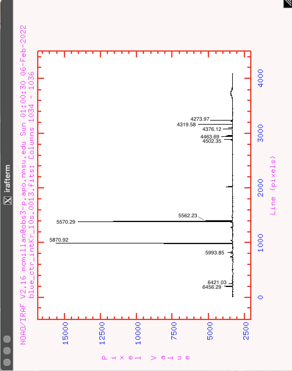
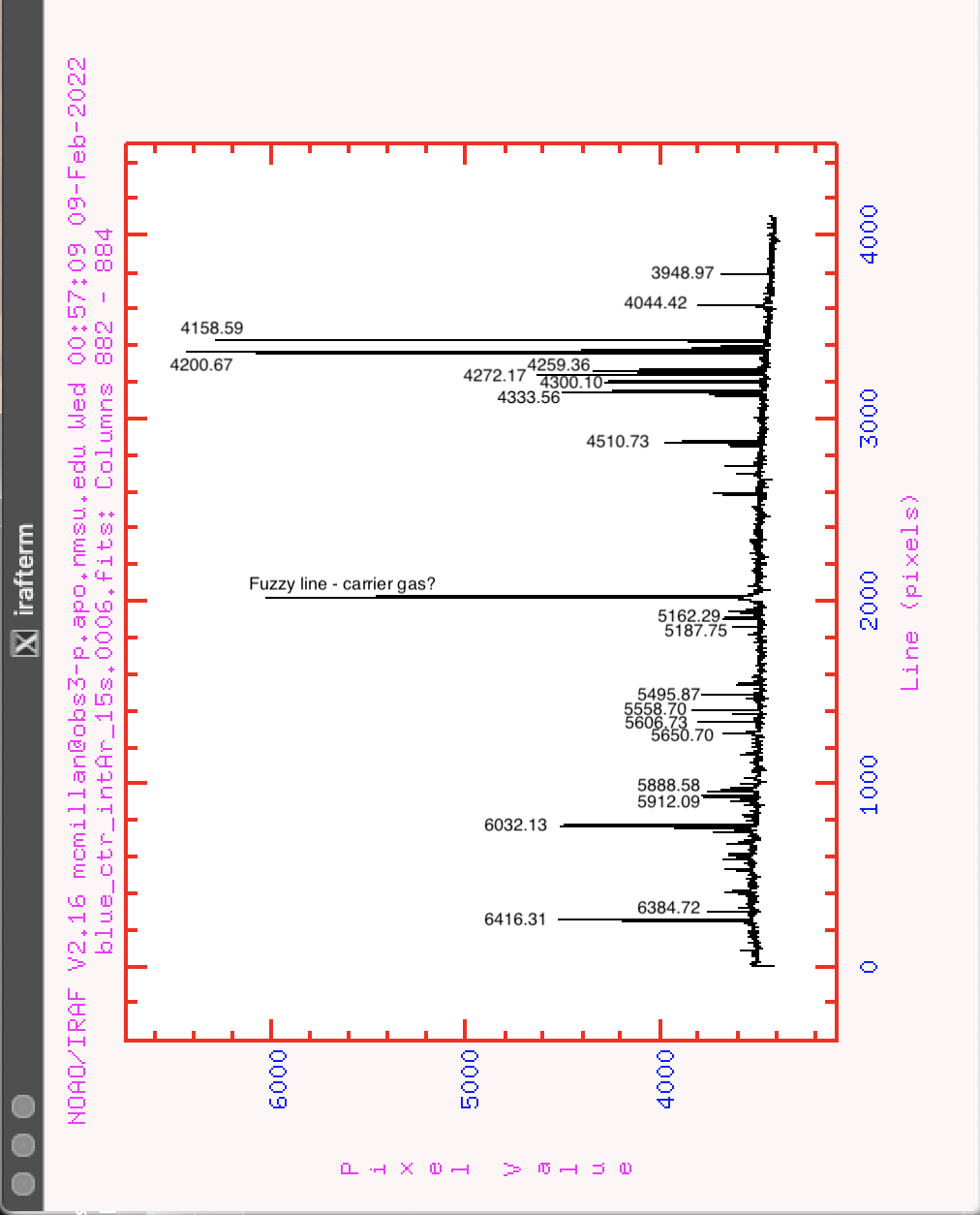
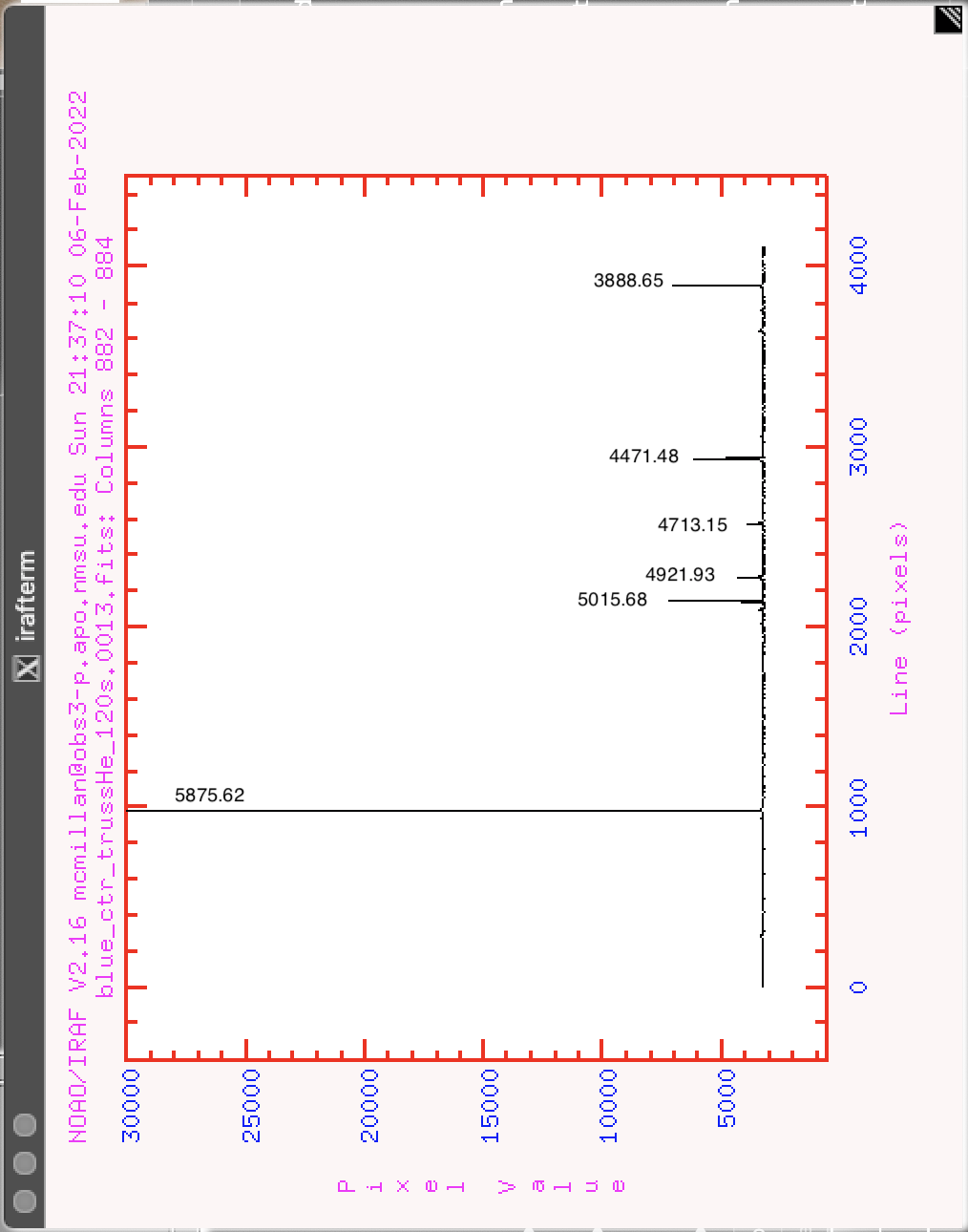
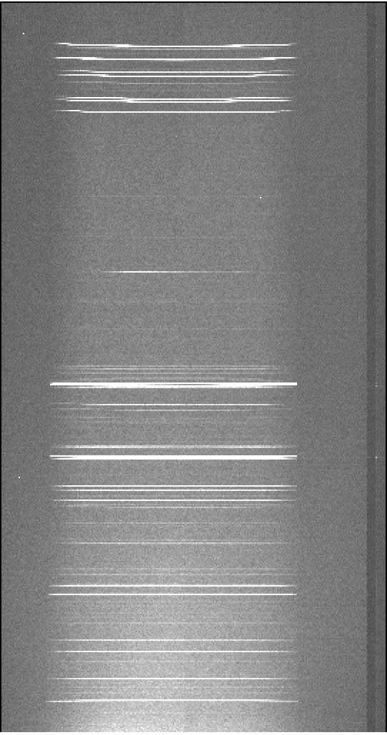
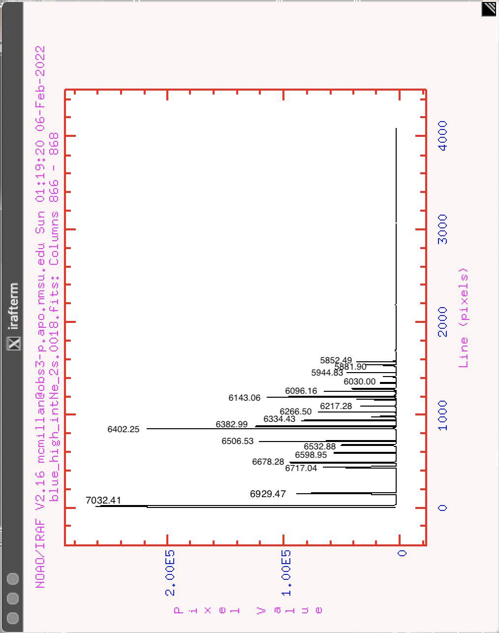
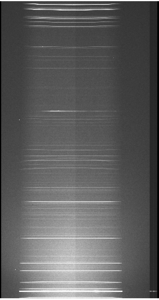
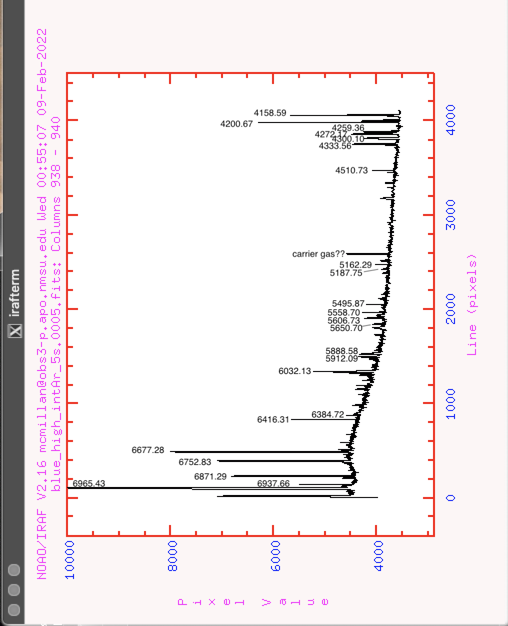
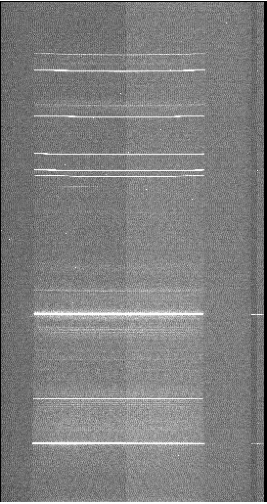
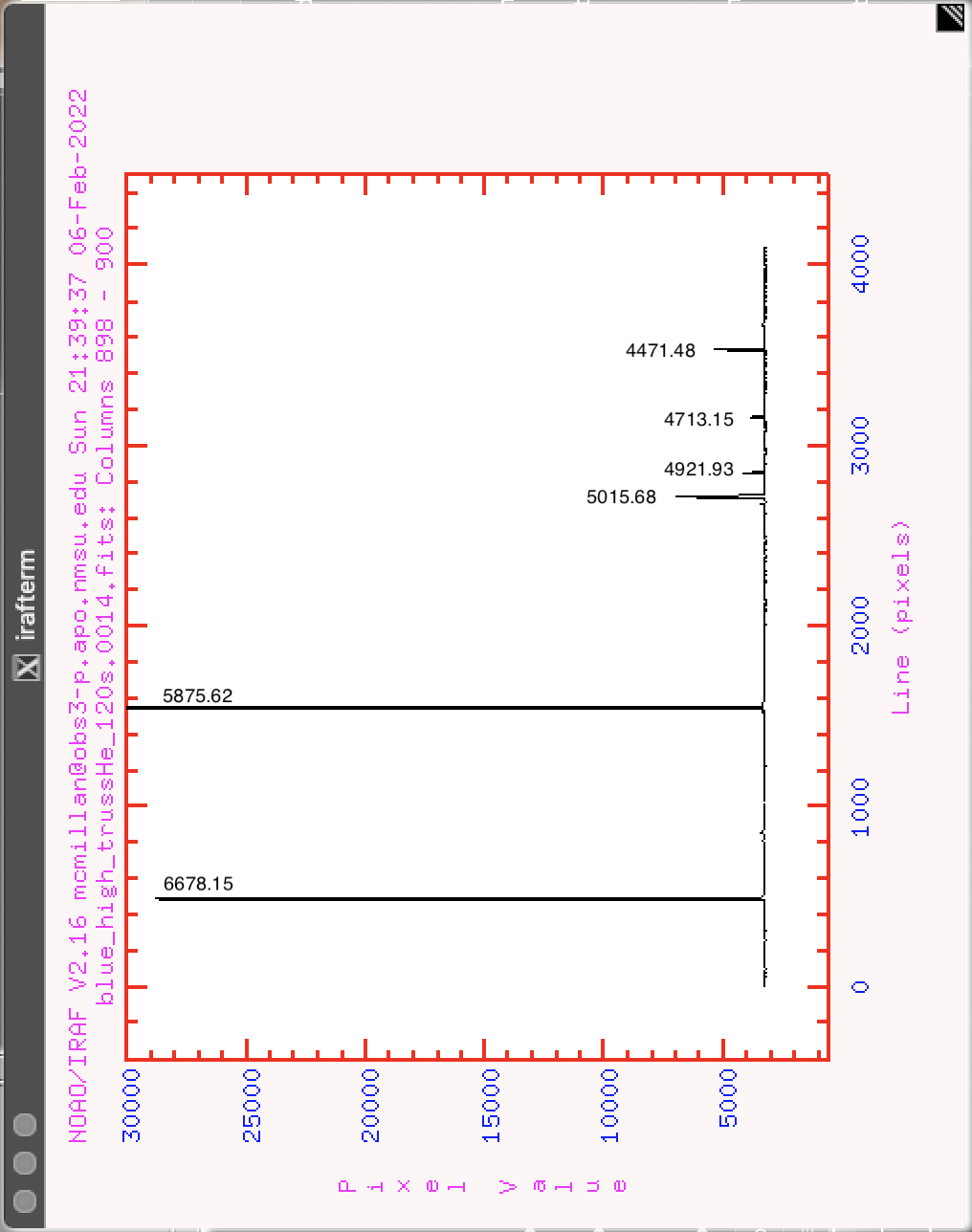
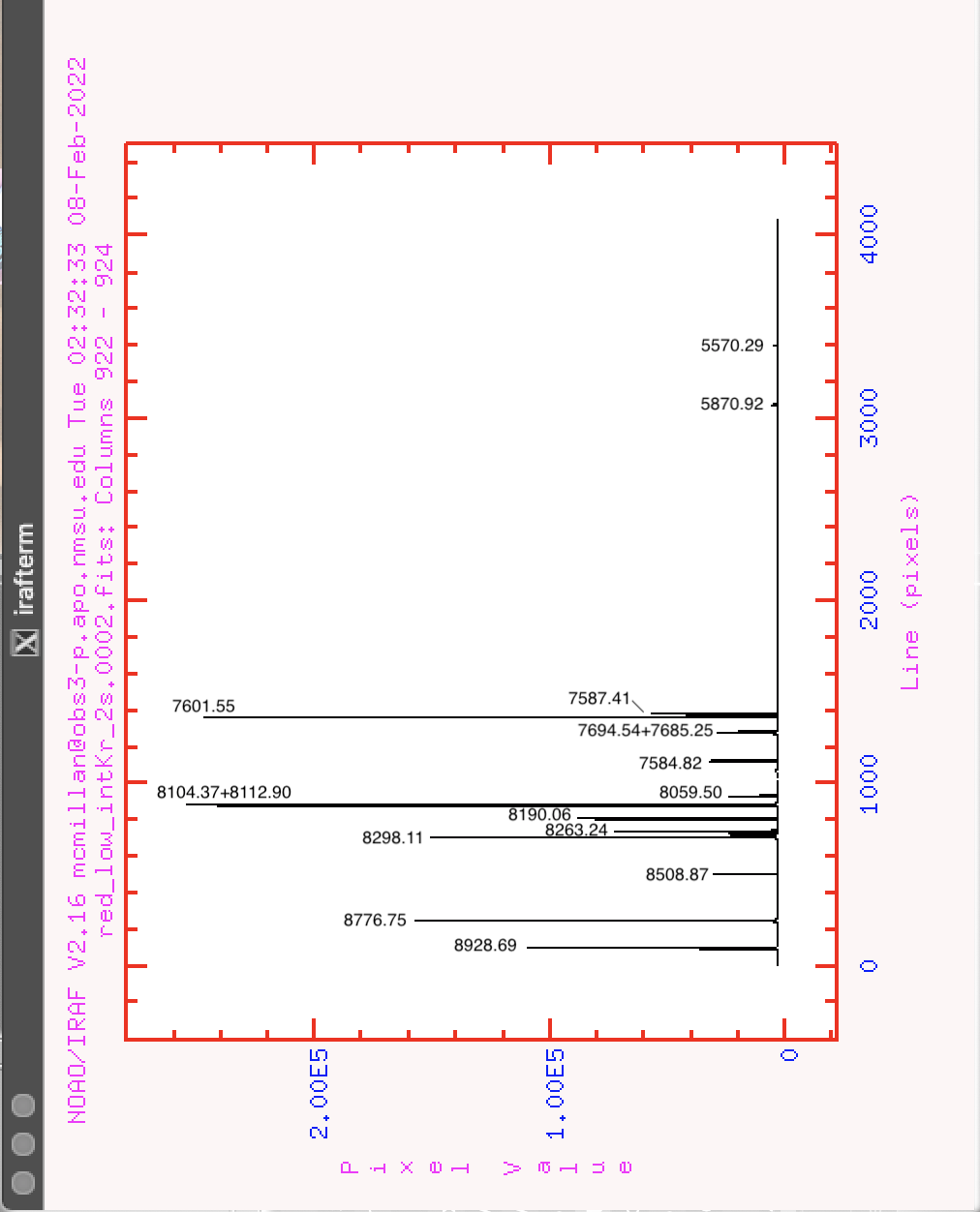
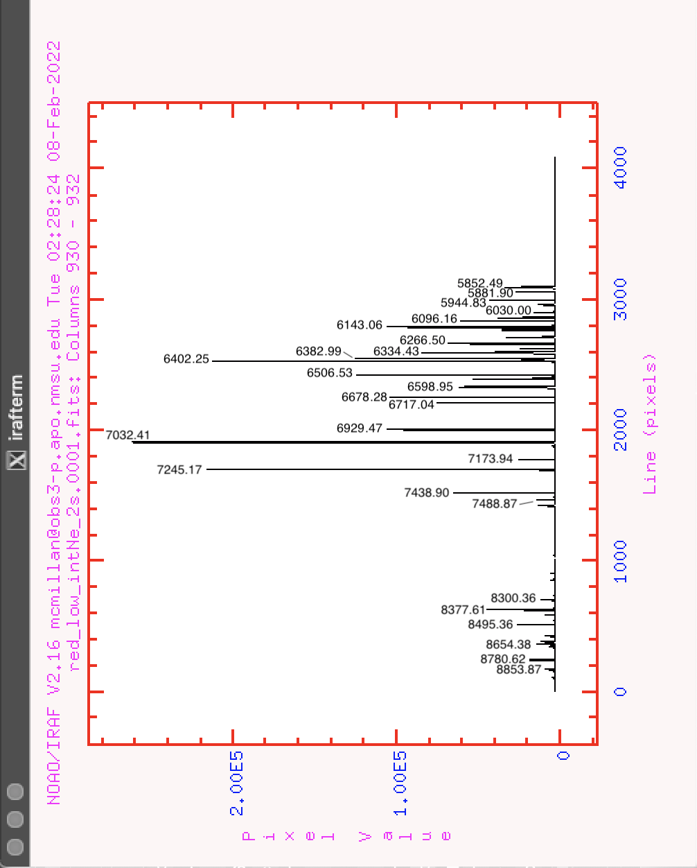
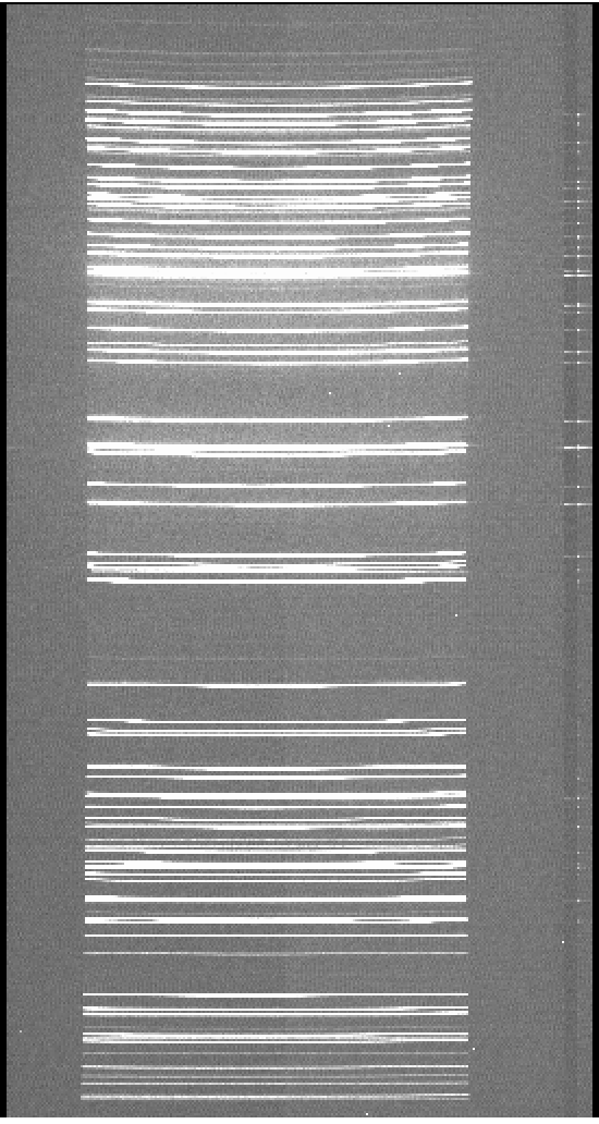
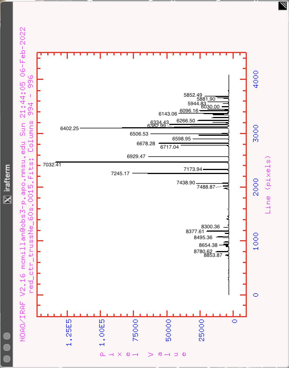
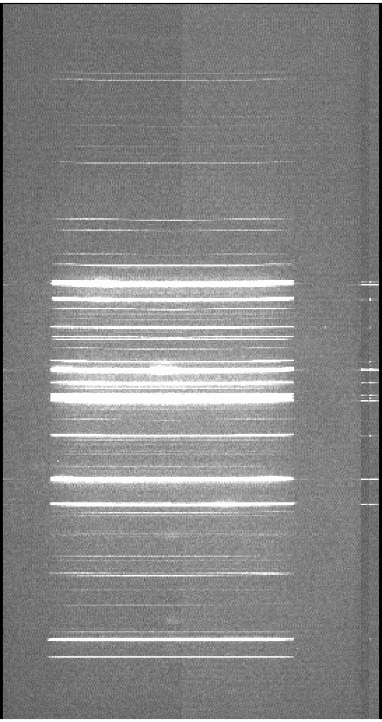
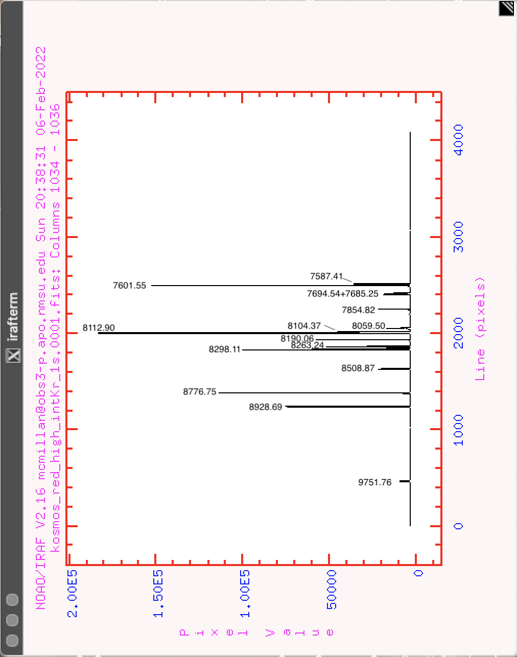
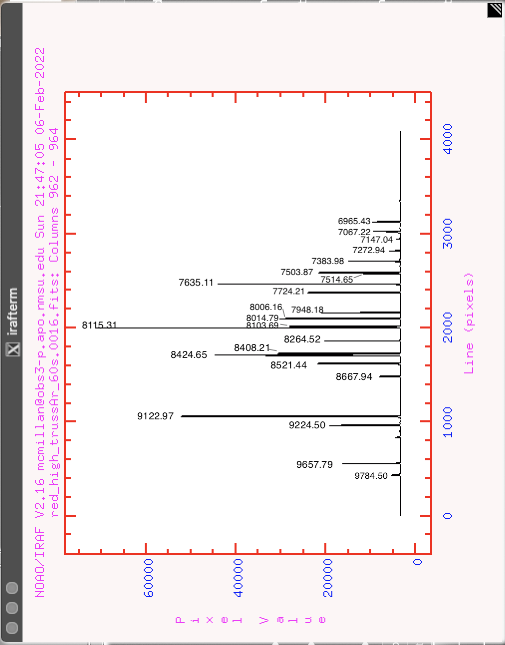
Wavelength calibration may be done with internal arc lamps (Ar, Ne, Kr) inside KOSMOS or with arc lamps (Ar, Ne, He) on the top of the telescope truss. The internal lamps have shorter exposure times but illuminate the slit at an angle; the truss lamps require longer exposure times but are similar to the illumination pattern for sky objects, so these lamps likely represent a more accurate rest wavelength. The KOSMOS spectrograph does have significant flexure as it rotates, which can move wavelengths by up to 5 pixels on the chip. Therefore, the recommended strategy is to take a full set of wavelength cals using both truss lamps and internal lamps at the start or end of the night; this provides a wavelength solution at rest wavelengths and also establishes the offset between internal and truss lamps. Then during the night, the faster internal lamps may be used for arcs at the position of each target object. If one object will be observed for multiple hours, an internal arc is recommended approximately every half hour. For observations in the red, it is possible that sky lines may serve as an alternative wavelength reference at each target position, but this approach is less useful for blue spectra because of the paucity of blue sky lines.
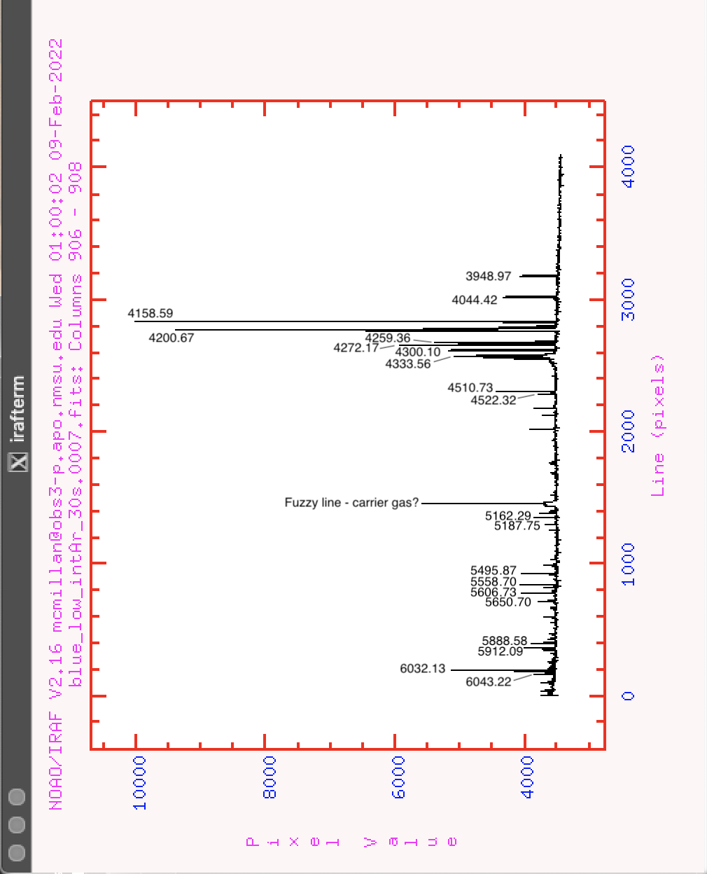
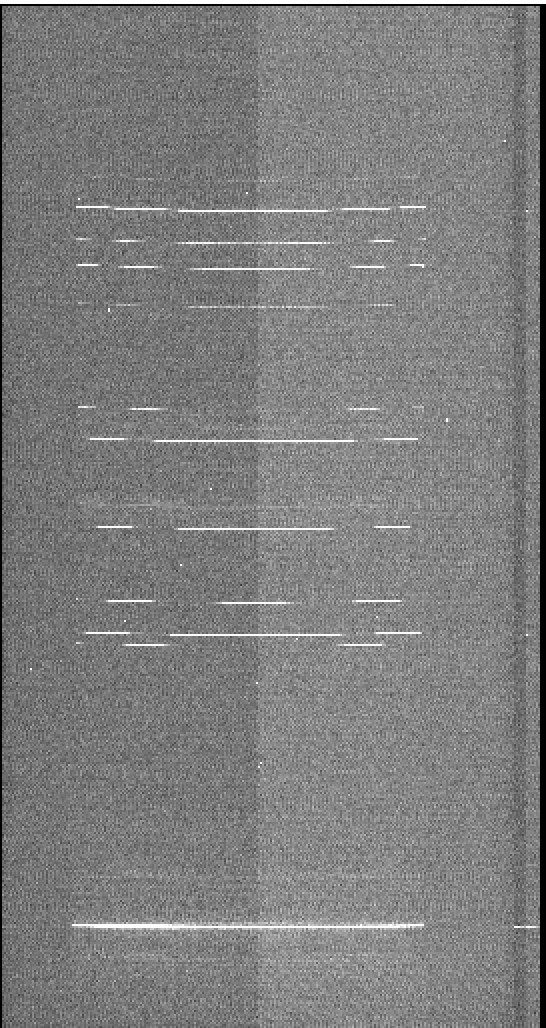
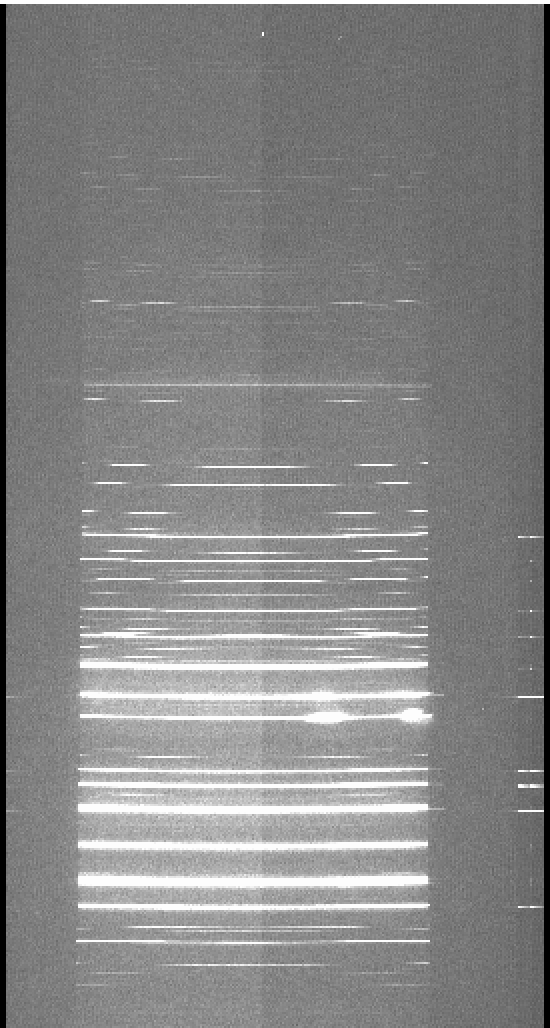
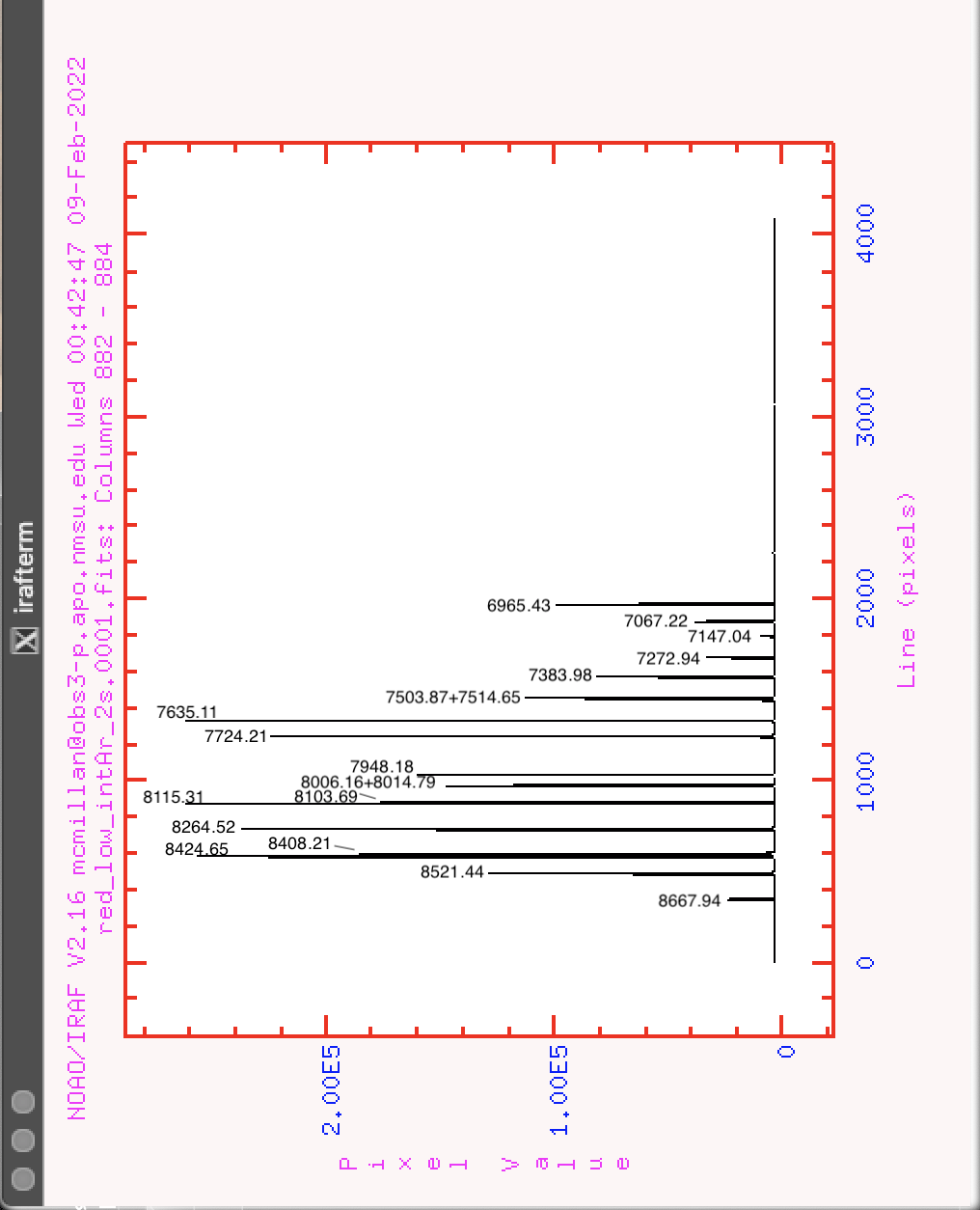
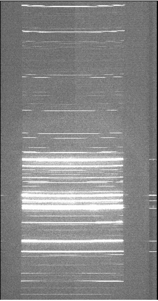
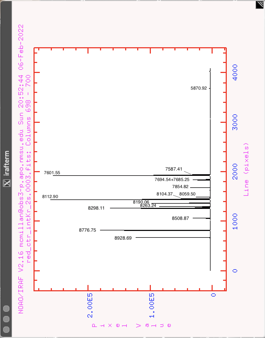
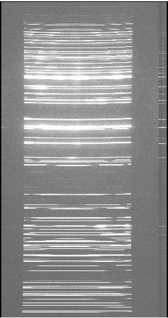
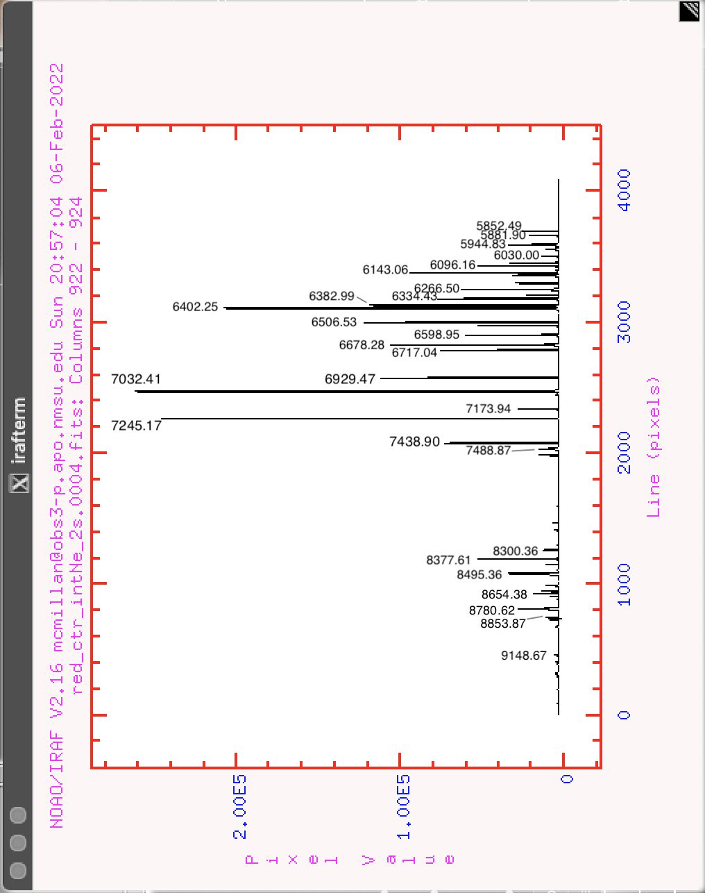
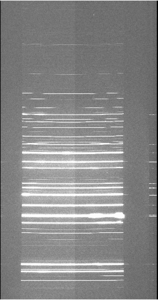
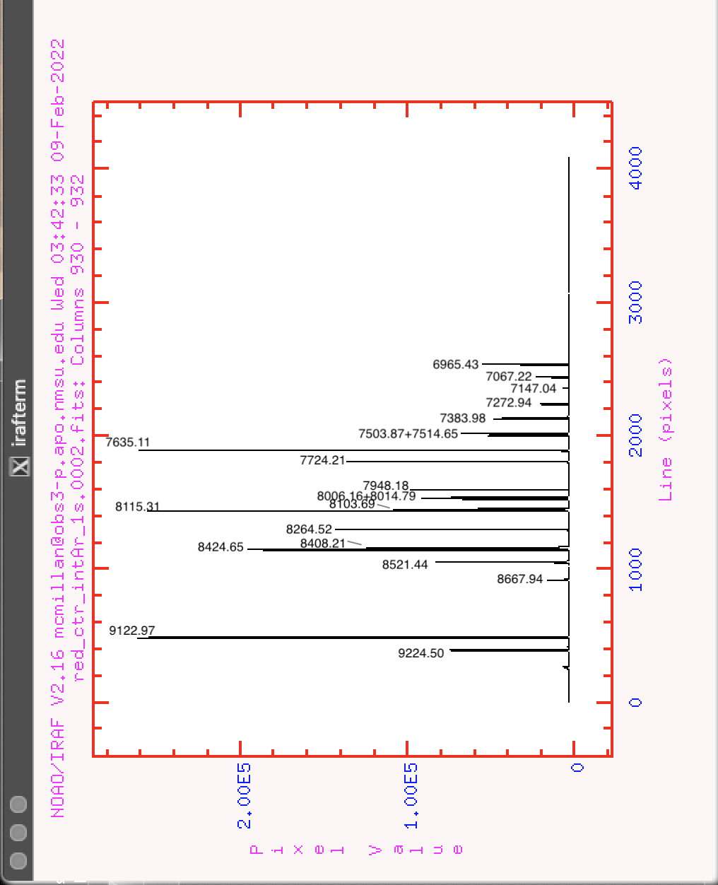
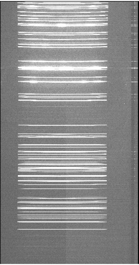
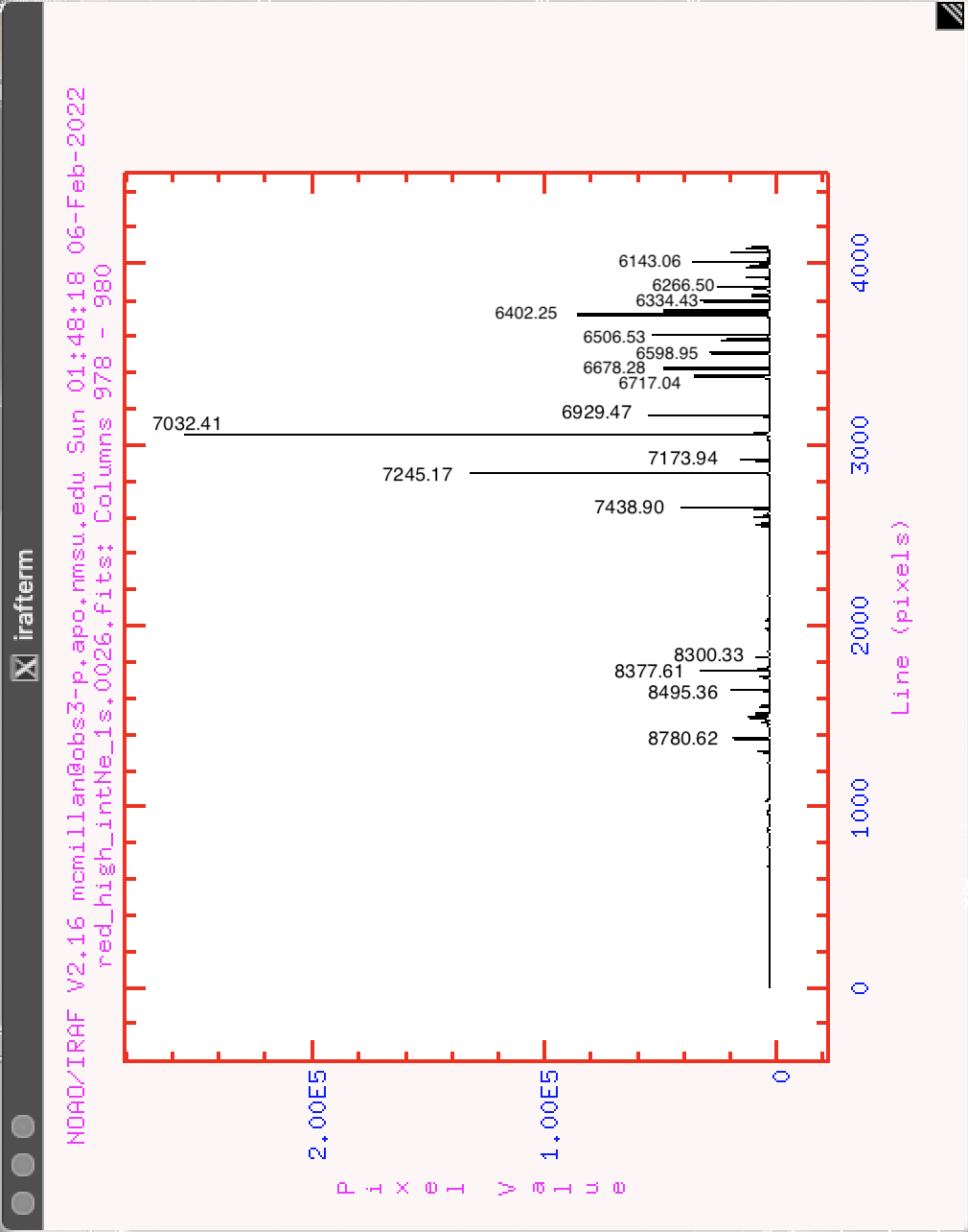
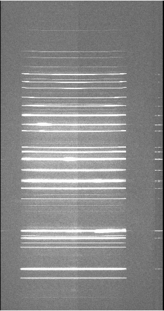
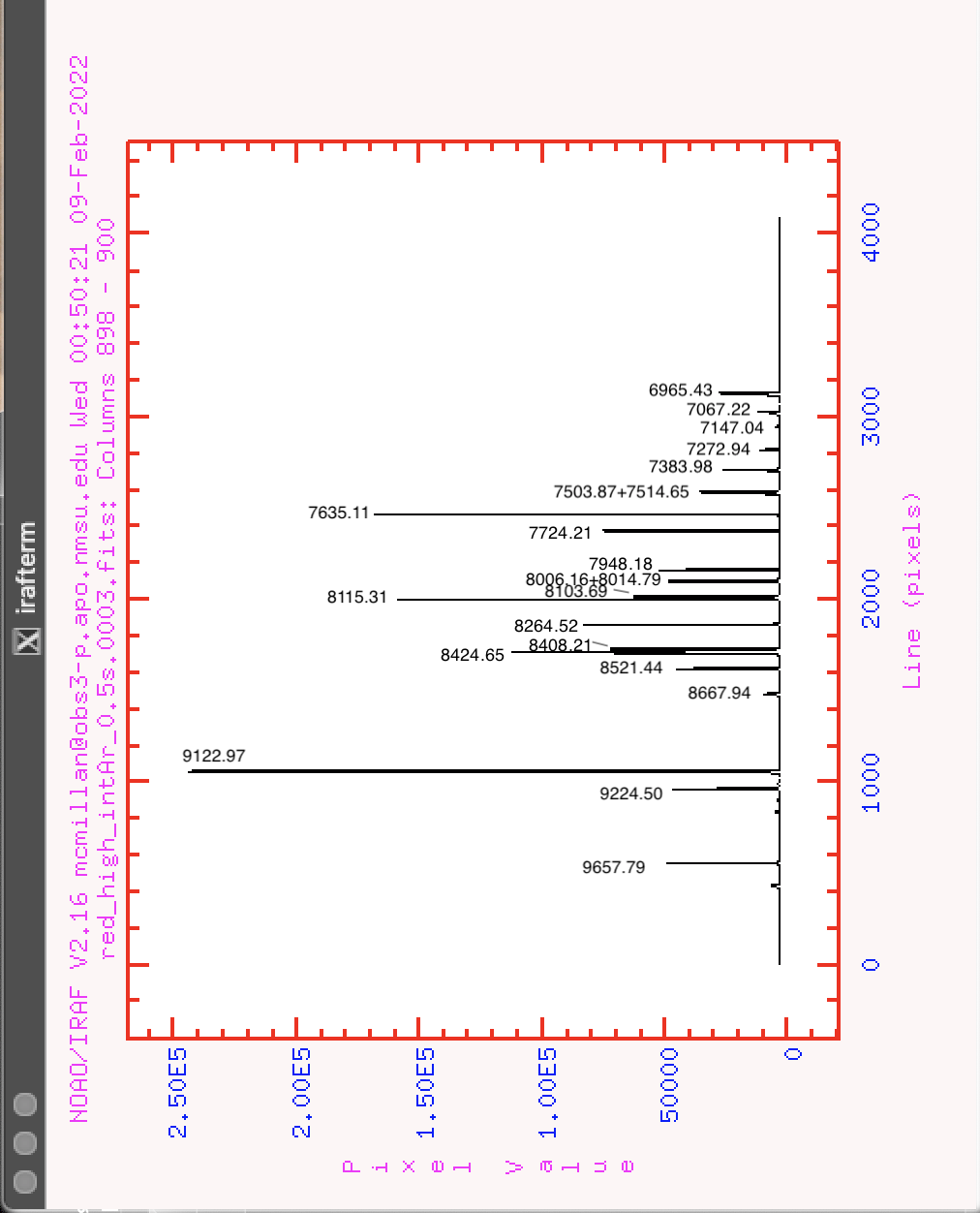
It is possible for all three lamps (truss Ar, Ne, and He; or internal Ar, Ne, and Kr) to be exposed at the same time, but for clarity the examples provided here show only one gas at a time. In general, He or Kr provide important lines for calibrating blue spectra, Ne has strong lines in the middle range of wavelengths, and Ar has some faint lines in the blue and brighter lines in the deep red. The suggested exposure times here may allow some of the brightest lines to saturate in order to make fainter lines measurable. These exposure suggestions are chosen for the set of 2" slits; narrower or wider slits will require adjusted exposures, which should scale inversely with slit size. In addition, lamp strength may vary, so it is always advisable to check your spectra and adjust exposures as needed.
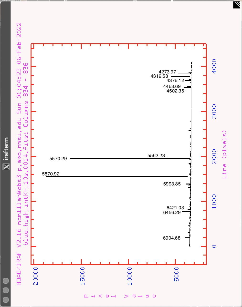
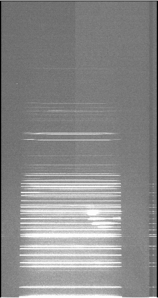
Grism Slit position Lamp Suggested exptime (2" slit) Examples Blue Low Internal Kr 30s image plot Blue Low Internal Ne 2s image plot Blue Low Internal Ar
45s image plot Blue Low Truss He 120s image plot Blue Low Truss Ne 120s? Blue Low Truss Ar 120s? Blue Center Internal Kr 30s image plot Blue Center Internal Ne 2s image plot Blue Center Internal Ar
45s image plot Blue Center Truss He 120s image plot Blue Center Truss Ne 60s Blue Center Truss Ar 180s Blue High Internal Kr 30s image plot Blue High Internal Ne 2s image plot Blue High Internal Ar
20s image plot Blue High Truss He 120s image plot Blue High Truss Ne 90s? Blue High Truss Ar 120s? Red Low Internal Kr 1s image plot Red Low Internal Ne 1s image plot Red Low Internal Ar 0.5s image plot Red Low Truss He 120s? Red Low Truss Ne 60s Red Low Truss Ar 90s Red Center Internal Kr 1s image plot Red Center Internal Ne 2s image plot Red Center Internal Ar 0.5s image plot Red Center Truss He 120s? Red Center Truss Ne 60s image plot Red Center Truss Ar 90s Red High Internal Kr 1s image plot Red High Internal Ne 1s image plot Red High Internal Ar 0.5s image plot Red High Truss He 120s? Red High Truss Ne 60s Red High Truss Ar 90s image plot
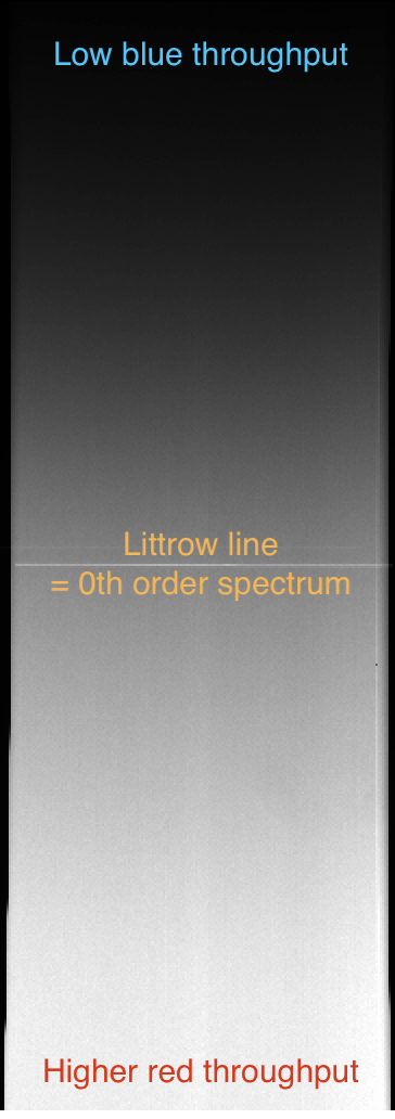
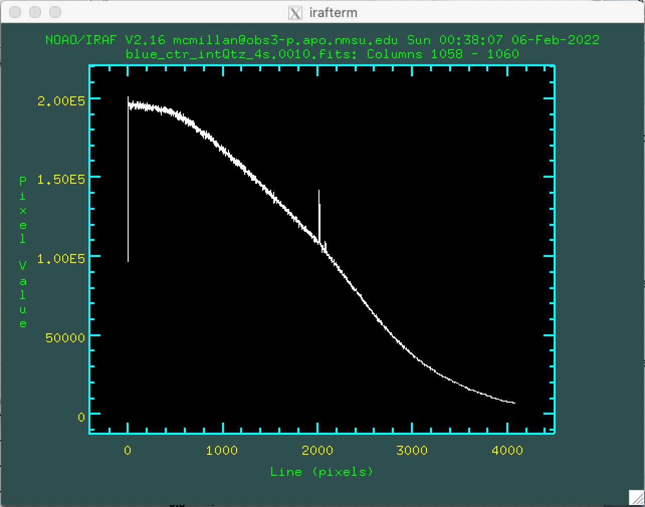
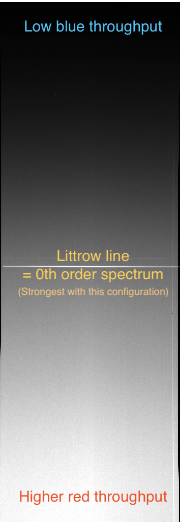
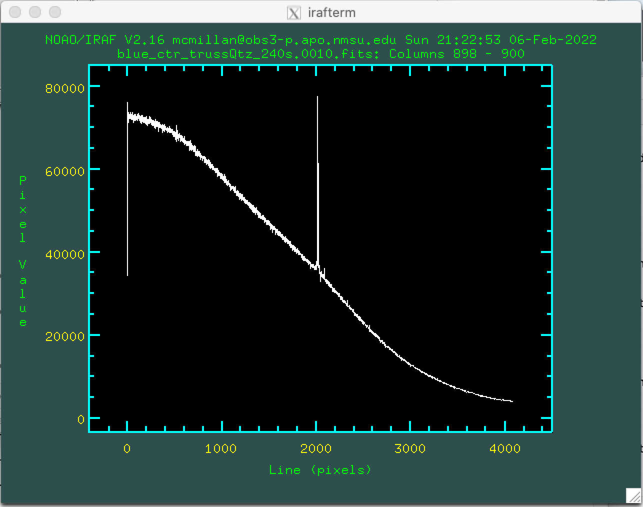
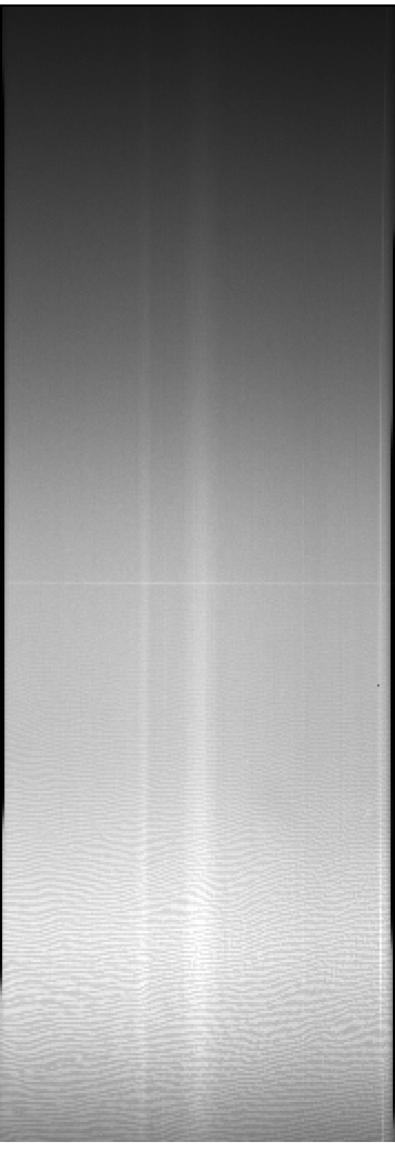
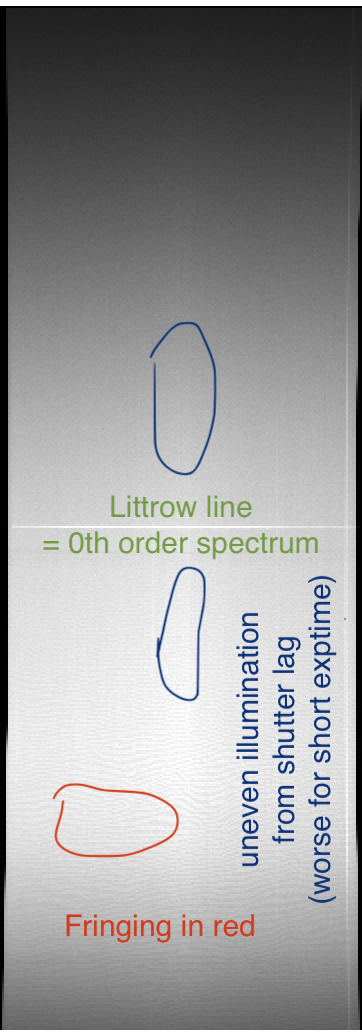
Two pairs of continuum quartz lamps (bright and dim) are mounted on the telescope truss, and a separate quartz lamp is available in the instrument for internal cals. Similarly to the arc lamps, the truss lamps require longer exposure times and the internal quartz lamp has a very short exposure time. As of early February 2022, there is an issue with lag in the spectrograph shutter which can cause uneven illumination in the spatial direction, particularly during cold weather. This effect occurs in all exposures, but poses more of a problem for shorter exposures, e.g. with the internal quartz lamp. If spatial flatness is desired, it may make more sense to take flats with the truss lamps rather than the internal lamp. There should be no need to take flats at every telescope position, so only one set of flats should be needed during the night. All flats with any continuum lamp will include a bright line at the Littrow position where a 0th-order undispersed spectrum passes through the grism; the strength of the Littrow line varies depending on angle of illumination, with the strongest line produced for the blue grism with the center slit position illuminated by the truss BrQtz lamp.
The following table has suggested exposure times and example flats for each grism and slit position.
| Grism | Slit position | Lamp | Suggested exptime (2" slit) | Examples |
|---|---|---|---|---|
| Blue | Low | Internal Qtz |
120s | |
| Blue | Low | Truss BrQtz |
240s | |
| Blue | Center | Internal Qtz |
80s | image plot |
| Blue | Center | Truss BrQtz |
240s | image plot |
| Blue | High | Internal Qtz |
50s | |
| Blue | High | Truss BrQtz |
240s | |
| Red | Low | Internal Qtz |
20s | |
| Red | Low | Truss BrQtz |
90s | |
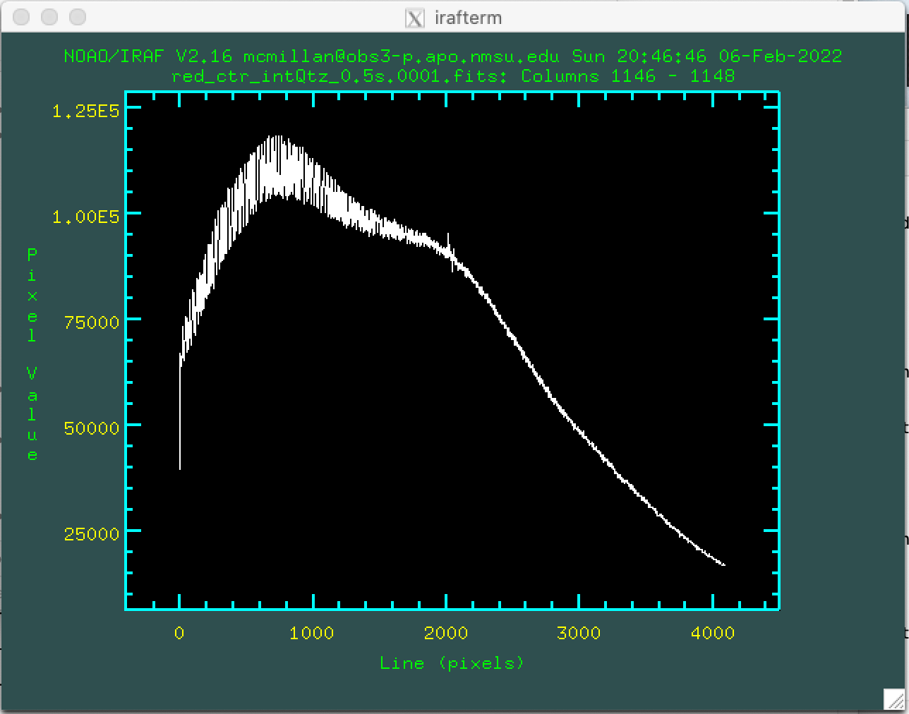
| Red | Center | Internal Qtz |
15s | image plot |
| Red | Center | Truss BrQtz |
60s | image plot |
| Red | High | Internal Qtz |
15s | |
| Red | High | Truss BrQtz |
60s |
The plots and exposure times are for slits around 2" wide; for other slits, the exposure times should be adjusted inversely with slit size.
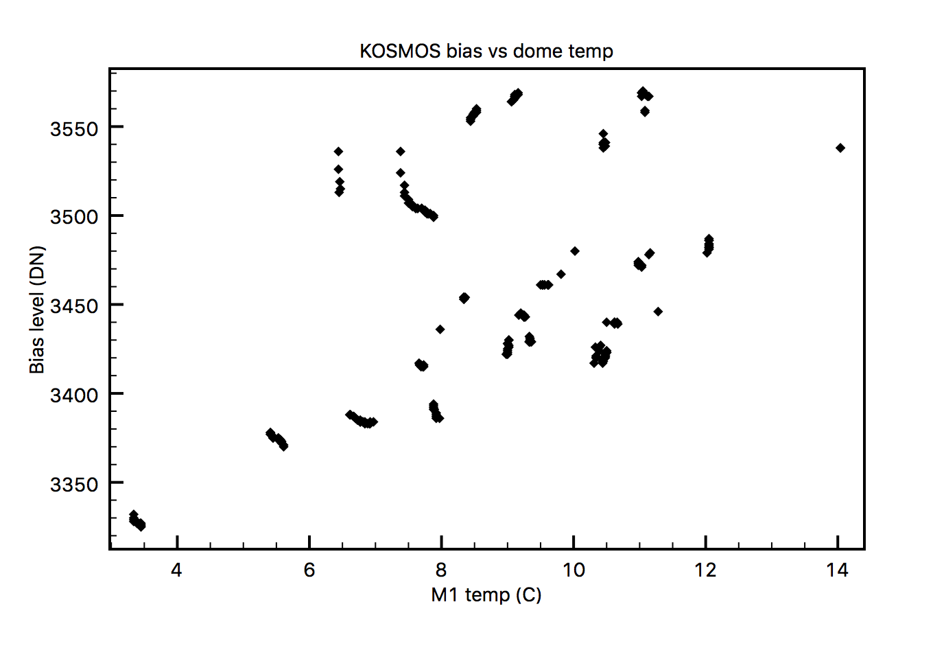
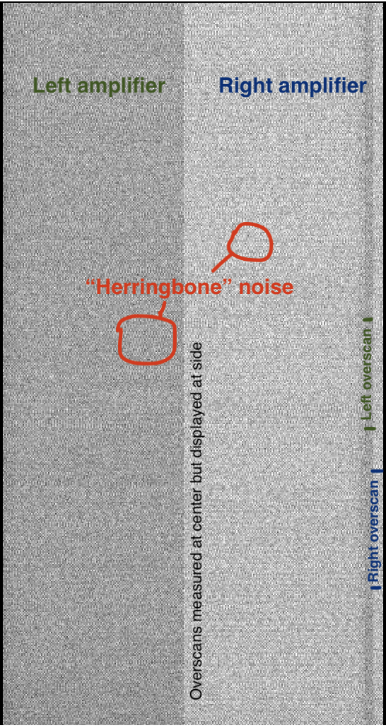
KOSMOS Bias levels are between 3000 to 4000 DN, and can vary by hundreds of DN within the course of a night or seasonally. The cause of the variation is not well understood; some of the variation is correlated with dome temperature and therefore the temperature of the readout electronics; some variation happens on short timescales, including within a single sequence of bias images. Rarely, a ramp or step function will appear in a single bias image. The normal solution to a wandering bias level would be overscan subtraction of every science image. However, there are some issues with the overscan as well, discussed below.
There is a pattern noise present in bias images and in low-background levels of science images; this has been described as a "herringbone" pattern which may be tens of DN from peak to peak. Pattern noise can be extremely difficult to eliminate from electronics, and similar noise was noted in the instrument when it was in use at KPNO. The best way to deal with this sort of noise is to combine multiple images together, and as long as the pattern moves from image to image, the peaks and valleys should average out.
Note that the chip heater does not run during readout and therefore it does not run during a long sequence of biases. Chip temperature may change by more than 10 K during a sequence of 20 bias images. For this reason, it is recommended to take shorter bias sequences of perhaps 5 images at a time, and wait a minute or so before starting another sequence of biases or before taking darks.
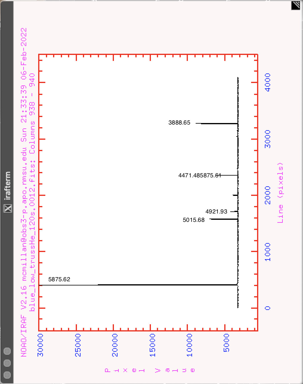
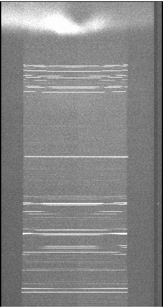
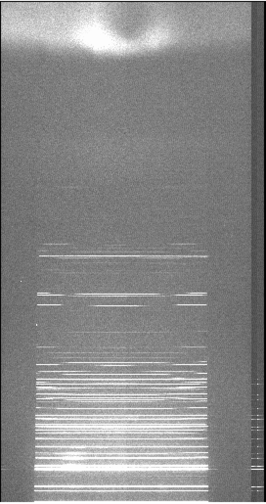
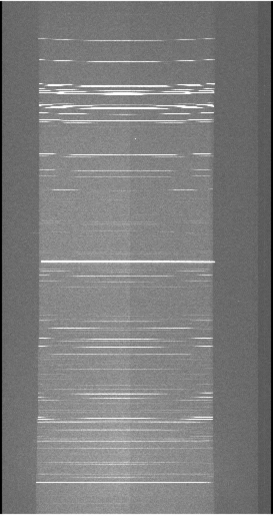
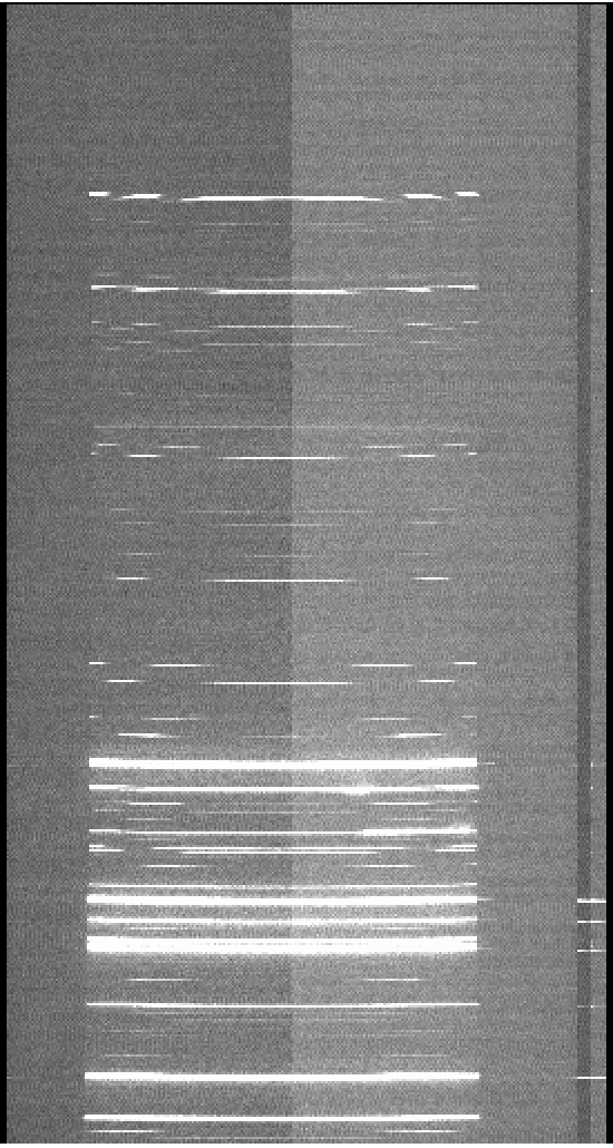
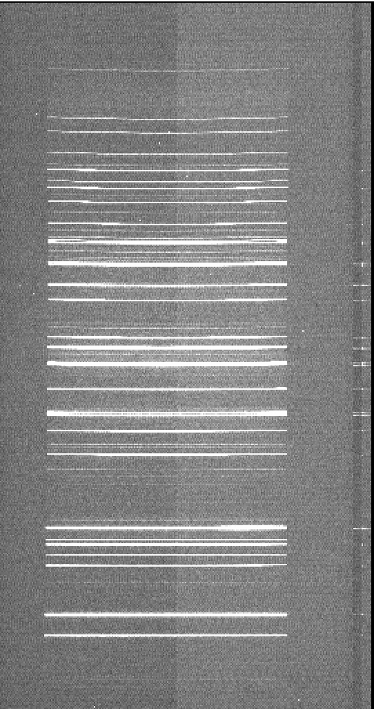
There are two overscan sections, one for each amplifier, each section 50 columns wide. The amplifiers read from the outside of the chip inward, therefore both overscans are read immediately after the central section of the image, but they are displayed at the right side of the image. As of February 2022, there is a problem with poor Charge Transfer Efficiency, particularly following saturated pixels. This means that when a part of the chip is saturated, the overscan section (measured immediately after the illuminated pixels in the center of the chip) will have leftover charge. The proper solution for a problem with CTE is adjusting clock voltages on the chip, which we are trying to arrange. Until that adjustment can be made, observers are advised to use care in defining the overscan to be used, especially for any image that includes strong emission lines (including sky lines). A simple bias level for each image may determined by using the overscan near the top or bottom of the image, or any area where illumination levels are low. Subtracting overscan from each row of the image may be unhelpful, but if the observer feels this is necessary, be sure to use the last few columns of the overscan furthest from the illuminated pixels.
Here is an example arc spectrum showing the CTE problem in the overscan of rows which include bright lines:
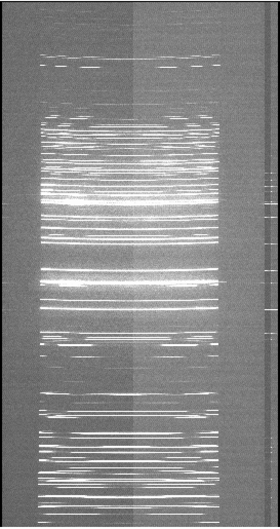
As of early February 2022, the image sections are not reflected in the image header; header cards are provided below for each binning configuration. However, care should be used in the definition of the overscan section, since the entire overscan may not be usable as discussed above.
1x1 binning BINX = 1 BINY = 1:
CSEC11  = '[1:1024,1:4096]'    / data section of CCD (unbinned)
DSEC11  = '[1:1024,1:4096]'    / data section of image (binned)
BSEC11  = '[2049:2098,1:4096]' / bias section of image (binned)
CSEC12  = '[1025:2048,1:4096]' / data section of CCD (unbinned)
DSEC12  = '[1025:2048,1:4096]' / data section of image (binned)
BSEC12  = '[2099:2148,1:4096]' / bias section of image (binned)
1x2 binning aka spectral binning; column binning = BINX = 1, row binning = BINY = 2
CSEC11  = '[1:1024,1:4096]'    / data section of CCD (unbinned)
DSEC11  = '[1:1024,1:2048]'    / data section of image (binned)
BSEC11  = '[2049:2098,1:2048]' / bias section of image (binned)
CSEC12  = '[1025:2048,1:4096]' / data section of CCD (unbinned)
DSEC12  = '[1025:2048,1:2048]' / data section of image (binned)
BSEC12  = '[2099:2148,1:2048]' / bias section of image (binned)
2x1 binning aka spatial binning; column binning = BINX =2, row binning = BINY = 1
CSEC11  = '[1:1024,1:4096]'    / data section of CCD (unbinned)
DSEC11  = '[1:512,1:4096]'    / data section of image (binned)
BSEC11  = '[1025:1074,1:4096]' / bias section of image (binned)
CSEC12  = '[1025:2048,1:4096]' / data section of CCD (unbinned)
DSEC12  = '[513:1024,1:4096]' / data section of image (binned)
BSEC12  = '[1075:1124,1:4096]' / bias section of image (binned)
2x2 binning BINX = 2 BINY = 2
CSEC11  = '[1:1024,1:4096]'    / data section of CCD (unbinned)
DSEC11  = '[1:512,1:2048]'    / data section of image (binned)
BSEC11  = '[1025:1074,1:2048]' / bias section of image (binned)
CSEC12  = '[1025:2048,1:4096]' / data section of CCD (unbinned)
DSEC12  = '[513:1024,1:2048]' / data section of image (binned)
BSEC12  = '[1075:1124,1:2048]' / bias section of image (binned)
Dark current on KOSMOS is approximately 1 DN per minute. Observers taking long science exposures are advised to take darks at the same exptime as their longest exposure to measure the dark current behavior on the observing night; this may then be scaled down to match shorter exposures, if needed. Darks are best taken with the calstage in and the dome dark, and the instrument does not need to be mounted to the telescope. So far, we have not seen problems with darks taken while the instrument was being moved or filled, but it is still a reasonable precaution to wait to start darks until the instrument is still.
If you wish to do relative flux calibration for your spectra, you will need to observe some spectrophotometric standards. Information about some standards can be found here.
A TUI catalog of the standard stars described on the above standards page.
Be sure to turn off any calibration lamps you may have used, then hand over the instrument by simply quitting out of the KOSMOS instrument control window in TUI. In some circumstances, you may continue to use the instrument after your shift, e.g., you are the first half observer and the scheduled second-half observer is not using KOSMOS. Ask your observing specialist for permission to do so if circumstances warrant.
5.1. Data Storage and Retrieval
Your data will remain on arc-gateway.apo.nmsu.edu:/export/images/your program code/UTYYMMDD/ for 9 to 12 months before being automatically deleted. Data can be accessed using scp or sftp to the institutional observer accounts on arc-gateway (you can also use ftp and the images account and password); call APO (575-437-6822) if you are unsure of the correct login.