
APO SITE AIR COMPRESSOR SYSTEMS
There
are 2 separate compressed air systems on site that function independently.
These systems can backup each other in case of an emergency. Depending on the
situation the backup system can support operations for either a short time or
for days.
System No. 1: This system provides compressed air to:
3.5m
primary mirror support
2.5m --all
1m -- all
.6m -- all
Ops
bldg outlets
System No. 2: This system provides compressed air to:
Shop
Garage
3.5m
Eyelids/Mirror Cell
3.5m
Enclosure lock
3.5m
Instrument purges
.5m
Back-up PMSS pumps
System No.1
Compressed air is
provided by two Kaeser screw compressors in the
boiler room. Each compressor can
handle the load by itself and runs for 12 hrs each day, then switches over to
the other compressor. Air from the
compressors goes into an air tank in the boiler room. The air is filtered and
dried in the boiler room before being distributed. There are additional air
tanks at the 3.5m ground level, 2.5m, 1m, and .6m telescopes. Pressure runs at
either 109 or 115 psi depending on which compressor is operating. Each compressor and dryer system
provides automatic redundancy. If
the load becomes too much for one compressor to handle (pressure drops due to
leak for instance) then the second compressor will come on load automatically.
There are 3 operating
modes for these compressors:
On
load –generating compressed air;
Off
Load – motor running but not building pressure;
Standby-
motor off unless pressure drops.
The largest consumer of
this air is the 2.5m PMSS system.
The air tanks are sized
to provide 15 minutes of compressed air to support the mirrors in the event of
a compressor fault.
There are two
alarms: A low pressure alarm in
the Ops Building extension on the north facing wall which alerts if the
pressure drops below 85 psi; and an alarm in the shipping/receiving area of the
Ops Bldg Service Area which alerts if there is too much moisture in the air.
(This is critical for the instrument purge systems in the 2.5m but not for
anything else) Both alarms need to
be addressed quickly.
In the event of loss
of pressure, both the 2.5m and 3.5m should be moved to zenith and held in that
position. Once the pressure drops
below 70 psi, do not slew either telescope in altitude.
The Kaeser
compressors operate via a computer SIGMA controller. Compressors labeled #1 and #2 are identical; compressor #3
is slightly different. If the
compressor senses a maintenance issue or is due for maintenance based on
runtime, an orange LED will blink by the wrench symbol. No immediate action is required.
If the compressor
faults, a red LED will blink. To clear this, you press the button with the two
half moon symbols. Then press the green “I” button to restart the compressor. If necessary, try recycling the power
using the circuit breaker behind each unit, then press the green “I”
button. If this fails, call for
assistance. (see Fig 1)
If the motor current
trips, common with power outages, you can reset this by opening the electrical
compartment on the right hand side of the compressor. There is high voltage in this compartment unless power has
been turned off. Turn the power
off (turn off circuit breaker behind unit), then open compartment using the
cross shaped key (see Fig 4). This
key is kept near each compressor.
Depress the blue reset button on the contactor. After depressing the blue button (see
Fig 5), close the compartment, turn circuit breaker on then, after the unit
initializes, press the green “I” button.
System No. 2
Compressed air is
provided by one Kaeser screw compressor in the
garage. There is also a Speedaire piston compressor that can be used as an
emergency backup. The Speedaire is not an automatic backup and requires a knife
switch be thrown to bring it on line.
(see Fig 3)
A twin tower dryer and
filters clean and dry the air before it leaves the garage. The Speedaire
tank is the only air storage tank for System No. 2.
There are currently no
alarms on System No. 2.
Systems No. 1 and No. 2
can be interconnected to provide an additional level of backup. Note that System No. 1 can back up
System No. 2 completely. However,
System No. 2 can only backup System No. 1 when operating on the Kaeser compressor.
********* Do not operate
System No. 1 on the Speedaire compressor. Doing so will burn up the Speedaire compressor within an hour ************
To operate System No. 1
from System No. 2:
Close
valve labeled “ Compressor 2 outlet NO” in boiler room
Close
valve labeled “ #1 outlet NO” in boiler room
Open the valve labeled “BU Supply NC” in the
boiler room (see Fig 2)
To operate System No. 2
from System No. 1:
Open the valve labeled “BU Supply NC” in the
boiler room (see Fig 2)
Anytime you operate both
systems from one source you need to conserve as much air usage as
possible. Avoid operating multiple
air devices simultaneously.
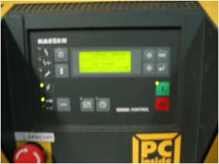
Figure 1
Kaeser screw compressor controller
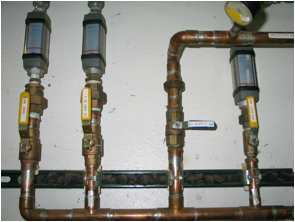
Figure
2
Back up supply valve
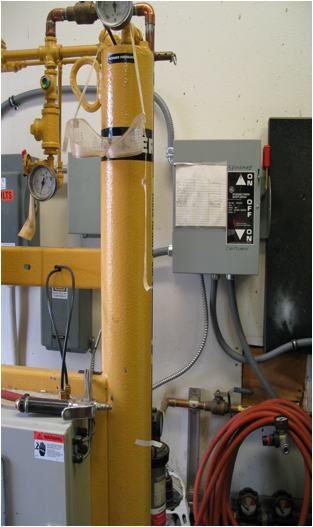
Figure
3
System
No. 2 backup knife switch (with
old craftsman legend)
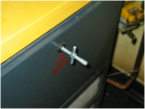
Figure
4
Electrical compartment above air filters (R/H side)
Shown with
key in latch
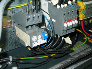
Figure
5
Motor current trip (blue reset button)
Inside compartment above air filter